If the voltage at which the reading becomes steady is
outside these limits, the regulator must be adjusted.
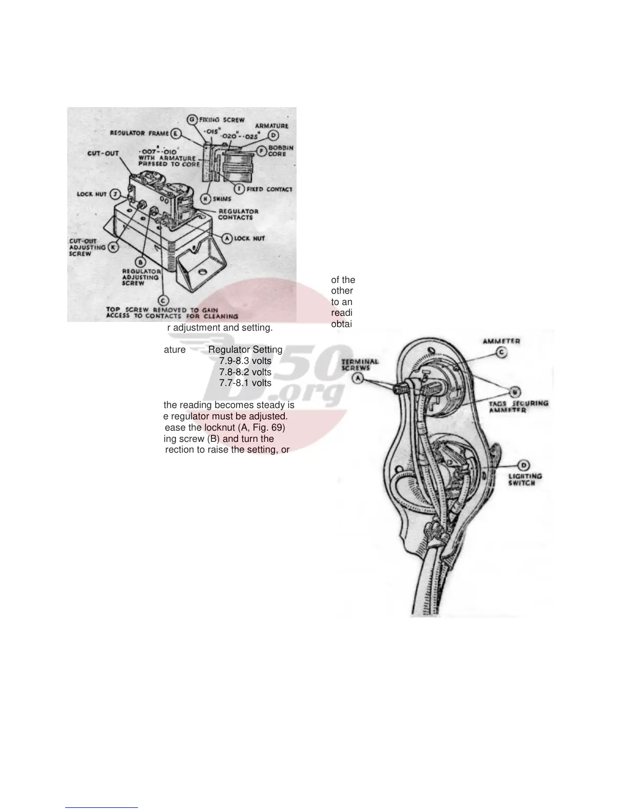
Shut off the engine, release the locknut (A, Fig. 69)
on the regulator adjusting screw (B) and turn the
screw in a clockwise direction to raise the setting, or
in an anti-clockwise direction to lower the setting.
Turn the screw a fraction of a turn at a time and then
tighten the locknut. When adjusting, do not run the
engine up to more than half-throttle, as while the
dynamo is an open circuit, it will build up to a high
voltage if run at a high speed and so a false
voltmeter reading would be obtained.
B (12) Regulator – Cleaning the Contacts.
After long periods of service it may be found
necessary to clean the vibrating contacts of the
regulator. These are accessible if the top screw (C)
securing the fixed contact is removed and the bottom
screw slackened to permit the fixed contact to be
swung outwards. The contacts (D) can then be
polished with a fine emery cloth.
B (13) Regulator – Mechanical Setting
The moving contact of the regulator is accurately set
and should not be removed. If, however, it does
become necessary to reset the contacts, proceed as
follows:-
Insert a .015” feeler gauge between the back of the
armature (D, Fig. 69) and the regulator frame (E).
Insert a .020” - .025” feeler gauge between the top of
the bobbin core (F) and the underside of the
moveable armature (D). (Not under the stop rivet).
Press the armature back against the armature frame
and down on to the top of the bobbin core with the
feelers in position and lock the armature in position
by tightening the two fixing screws (G).
Adjust the gap between the regulator contacts when
the armature is pressed down on the bobbin to
between .007” and .010”. This is done by either
inserting or removing shims (H) at the back of the
fixed contact (I).
Finally check and if necessary reset the electrical
adjustment of the regulator.
B (14) Cut-out
(a) If the regulator setting is within the correct limits,
but the battery is still not receiving current from the
dynamo, the cut-out may be out of adjustment or
there may be an open circuit in the wiring of the cut-
out and regulator unit.
(b) Remove the voltmeter lead from the “D” terminal
of the regulator unit and connect it to terminal “A”, the
other lead from the voltmeter must still be connected
to an earthing point. Run the engine as before: the
reading on the voltmeter should be the same as that
obtained when the
Fig. 70 Panel containing lighting switch and
ammeter, removed from headlamp.
For details of panel on DU42 headlamp fitted to later
models see Section C (6), page 46.
Voltmeter was connected to terminal “D”. If there is
no reading, the cut-out may be out of adjustment and
the contacts are not closing.
42