User Manual – Rev AJ California Instruments
covers. This can tak
and voltage rating. (
e the form of a panel-mounted socket (1 or 3 phase) of sufficient current
Not supplied with MX)
of
f
Cable lengths must not exceed twenty-five (25) feet. For lengths greater than 25 feet, calculate
the volta e drop
2 X DISTANCE X CABLE RESISTANCE PER FT. X CURRENT = VOLT DROP
The output power cables must be large enough to prevent a total voltage drop exceeding 1%
the rated output voltage between the power source and the load. Table 3-2 shows the size o
the cables that may be used. Note that wires must be sized to accommodate the maximum
current that is available. This may be a function of the voltage range and phase mode on some
MX models. If the MX has more than one output voltage range, size the wires for the lowest
available voltage range as the currents will be highest in that range.
g from the following formula:
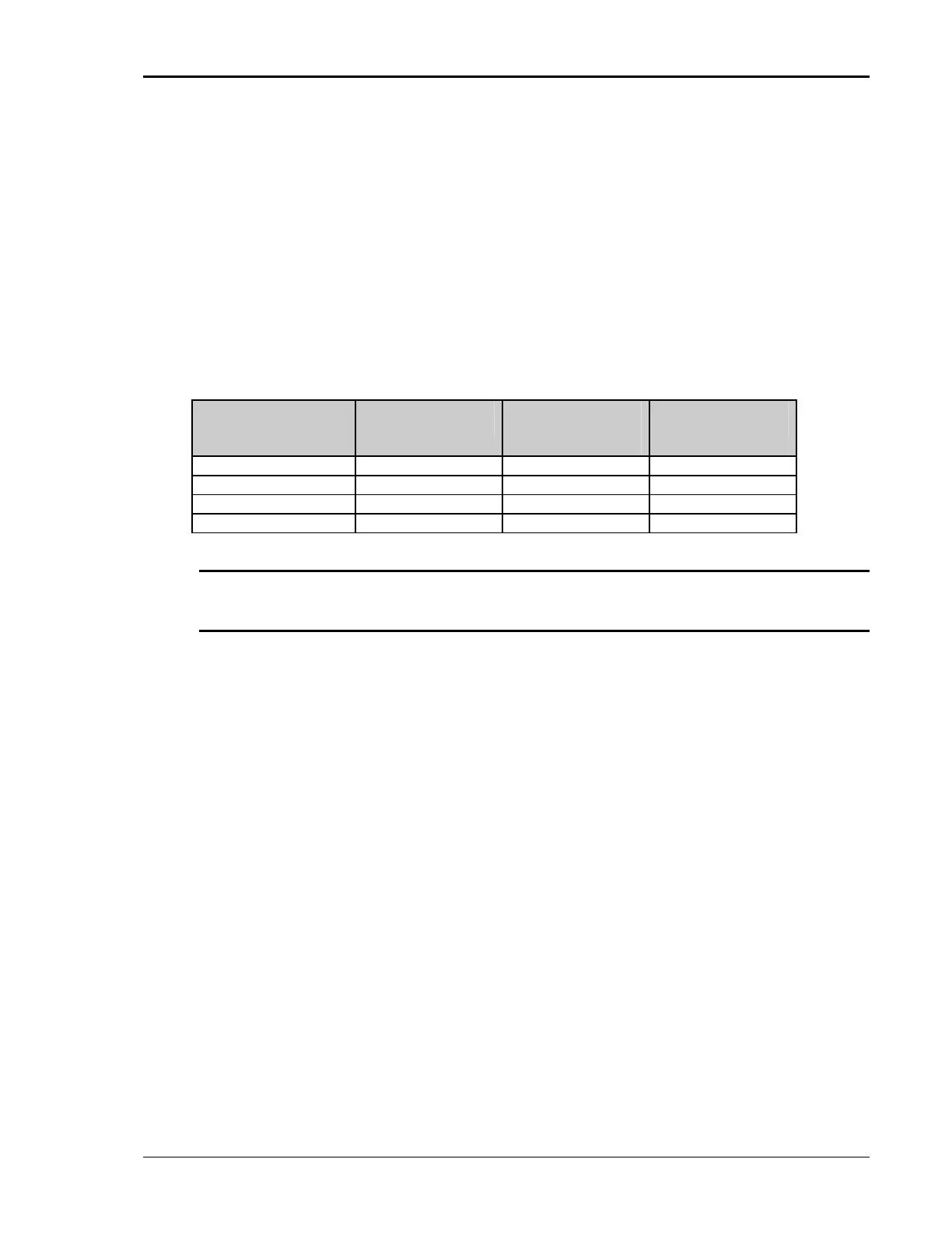
Table 3-2: Suggested Output Wiring Sizes *
Load Current Wire Gauge (US) Circular Mils
(kcmils)
Metric (mm2)
65 AMPS 6 AWG 26.24 13.3
130 AMPS 4 AWG 41.74 21.1
260 AMPS 1/0 AWG 105.6 53.5
400 AMPS 2/0 AWG 133.1 67.4
Note: high temper re rate ways consult the National Electrical Code Use atu d wire. Al
and/or local code regulations for proper rating and size of wire cabling prior to
installation.
MX Series 43