User Manual – Rev AJ California Instruments
3.6.7 Multi-Chassis Output Connections
If two or more MX chassis are used to form a
need to be combined (paralleled by phase). This can be done directly at the EUT if convenient
or usin he pro heav lti-chassis
MX systems, one 2-position blo
to be combined into one larger wire gauge size wire. The outputs of the 2 or 3 MX chassis are
connected on one side of these blocks (Phase A,B and C into the 3 position terminal and the
neutral into the 2 position terminal.). The EUT can be connected to the other side. Note that the
wire size to the EUT should be sized up to accommodate the double or triple currents per
phase
The d sions 4.
Note t even i put, the output neutrals of the MX chassis'
must be connected together for t
single power system, the outputs of all chassis
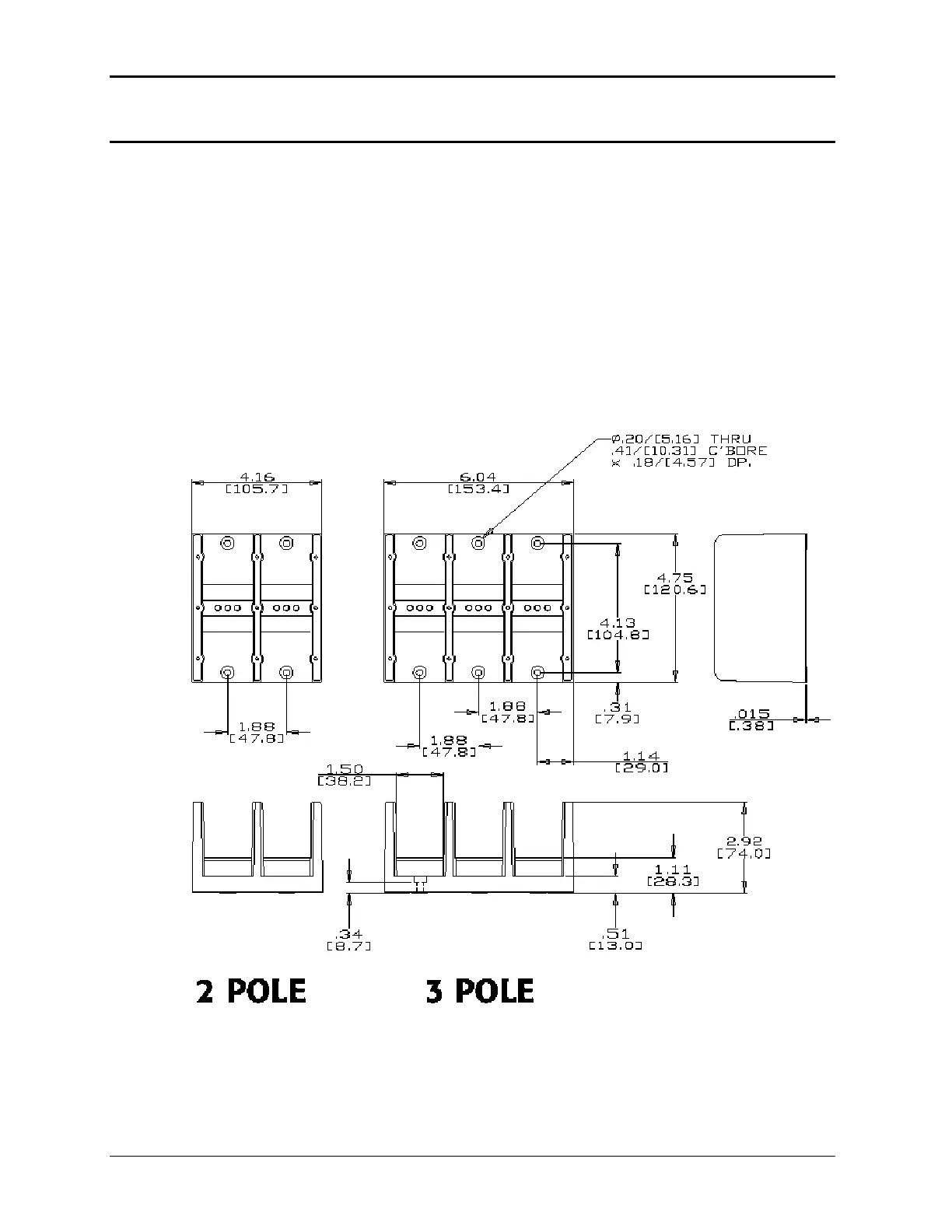
g t vided y-duty terminal blocks. Two blocks are provided with mu
ck and one 3-position block. These blocks allow up to four wires
.
imen of the supplied terminal blocks are shown in Figure 3-1
hat f the EUT is a three-phase delta in
he system to work correctly.
Figure 3-14: Ship kit Terminal Block dimensions
54 MX Series