2
2
2-20
2-20
Technology > Saddle Stitcher Unit > Controlling the Inlet Flappers > Overview
Technology > Saddle Stitcher Unit > Controlling the Inlet Flappers > Overview
■
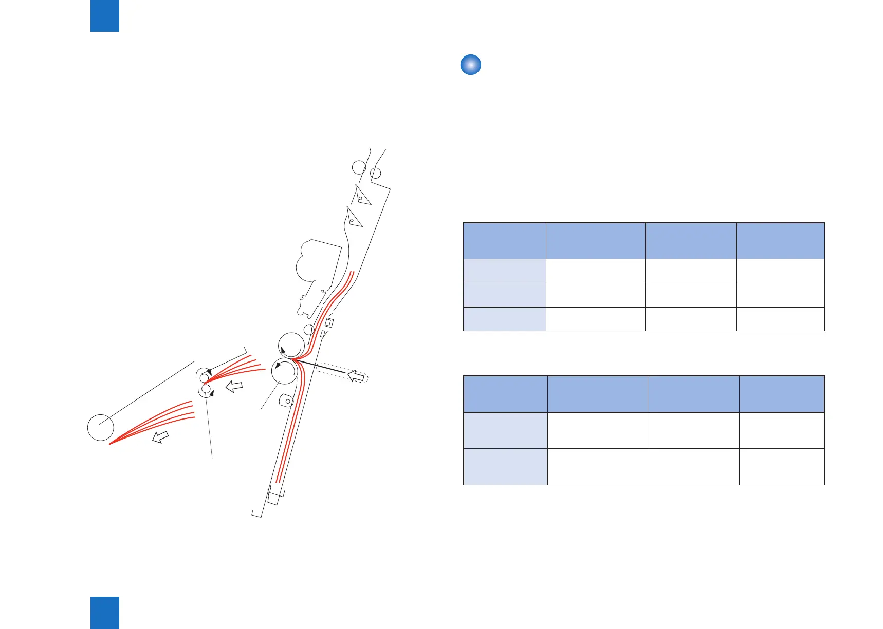
Folding/Delivering the Stack
The paper pushing plate pushes against the center of the stack to move it in the direction of
the paper folding rollers.
In response, the paper folding rollers pick the stack along its center and fold it in two.
The paper folding rollers together with the delivery roller then move the stack along to output
it on the delivery tray.
Delivery roller
Paper folding
roller
F-2-36
Controlling the Inlet Flappers
■
Overview
The two appers mounted at the paper inlet are operated to congure the feed path according
to the size of paper.
The appers are used to enable the following:
1. To detect the passage of the trailing edge of the paper being moved by an appropriate
sensor.
2. To prevent the following sheet from butting against the top of the existing stack,
The following table shows the relationship between sensors and paper sizes.
SENSOR A3
305mm×457mm(12×18)
279mm×432mm(11×17)
B4/LGL A4R/LTRR
No.1 paper sensor
(PI18)
Used Used Used
No.2 paper sensor
(PI19)
Not used Used Used
No.3 paper sensor
(PI20)
Not used Not used Used
Each apper is driven by its own solenoid.
The following table shows the relationship between solenoids and paper sizes.
Solenoid A3
305mm×457mm(12×18)
279mm×432mm(11×17)
B4/LGL A4R/LTRR
No.1 paper
deecting solenoid
(SL1)
OFF ON ON
No.2 paper
deecting solenoid
(SL2)
OFF OFF ON
T-2-4
T-2-5
 Loading...