2
2
2-36
2-36
Technology > Staple Operation > Stitcher Unit > Stitching Operation
Technology > Staple Operation > Stitcher Unit > Stitching Operation
Stitcher Unit
■
Stitcher
The stitcher base unit consists of two stitchers and stitcher bases.
The stitchers are xed in position, and are not designed to slide or swing.
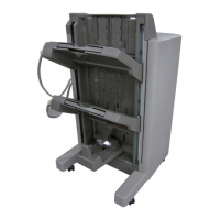
Stitching is executed by driving the rotary cam by the stitcher motor (M7, M6).
The front and rear stitcher units are operated with a time delay so as to prevent wrinkling of
paper and to limit the load applied to the power supply.
(A time delay for initiating the stitcher motor startup current helps decrease the load on the
power supply.)
The stitcher home position sensor (SW7, SW5) is used to monitor the movement of the rotary
cam, enabling identication of individual stitcher operations.
The presence/absence of staples inside the staple cartridge tted to the stitcher is detected
by the staple sensor (SW6, SW4).
The alignment plates keep both edges of the stack in place while stitching takes place.
Stitcher home position sensor
(front) (SW7)
Stitcher motor (front) (M7)
Stitcher motor (rear) (M6)
Stitcher home position
sensor (rear) (SW5)
No.1 paper sensor (PI18)
Alignment motor (M5)
Alignment Escape
Cam
Mount
F-2-79
■
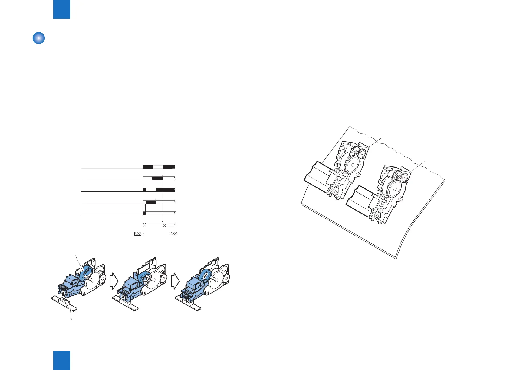
Stitching Operation
To enable stitching at two locations on a stack, two stitcher units (front, rear) are used.
Each stitcher unit is equipped with a stitcher motor (M7, M6) for drive, a stitcher home
position sensor (SW7, SW5) for detection of position and a staple sensor (SW6, SW4) for
detection of the presence/absence of staples.
The stitcher base is designed so that it may be drawn out to the front from the saddle stitcher
for replacement of the staple cartridge or removal of a staple jam.
The stitcher unit in sensor (PI16) is used to make sure that the stitcher base is properly tted
to the saddle stitcher.
Safety switches are not mounted for the stitcher unit (front, rear), as the location does not
allow access by the user.
Stitcher (rear)
Stitcher (front)
Stack
F-2-80