4
4
4-36
4-36
Parts Replacement and Cleaning Procedure > PCB > Removing the Saddle Stitcher Controller PCB
Parts Replacement and Cleaning Procedure > PCB > Removing the Saddle Stitcher Controller PCB
PCB
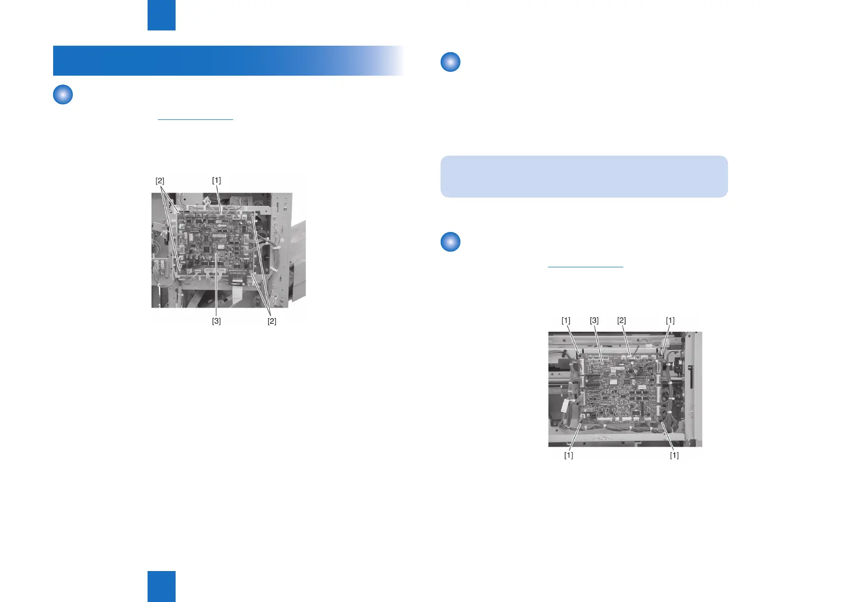
Removing the Finisher Controller PCB
1) Remove the rear cover.(Refer to page 4-14)
2) Disconnect all connectors [1] on the nisher controller PCB.
3) Remove four screws [2] and remove the nisher controller PCB [3].
F-4-74
Action on replacing the nisher controller PCB
1) Before replacing the nisher controller PCB, output the service mode setting values by
P-PRINT.
(LV.) COPIER> FUNCTION> MISC-P>P-PRINT
2) After nisher controller PCB exchange, input The value that did P-PRINT output into all
items of ADJUST/OPTION from a service mode.
NOET:
In this case, the counter cannot enter.
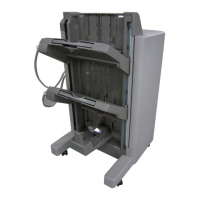
Removing the Saddle Stitcher Controller PCB
1) Remove the PCB cover.(Refer to page 4-18)
2) Remove the four screws [1] and 16 connectors [2], and remove the saddle stitcher
controller PCB [3].
F-4-75