2
2
2-35
2-35
Technology > Staple Operation > Stapler Unit > Stapling Operation
Technology > Staple Operation > Stapler Unit > Stapling Operation
●
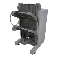
Second and Subsequent Sheets
The nisher controller PCB starts the swing motor (M106) and lowers the swing guide when
the rear end of the 2nd paper passes the 1st delivery roller.
The stack delivery motor is reversed.
The stack delivery motor rotates the stack delivery roller (upper) and return roller and sends
the paper to the processing tray.
At this point, the stack delivery roller (lower) does not rotate because the stack ejection lower
roller clutch (CL102) is disengaged.
The paper in the processing tray is detected by the processing tray paper sensor (PI108).
When the paper is delivered to the processing tray, the swing motor (M106) starts and raises
the swing guide.
When the swing guide home position sensor (PI105) detects the rising of the swing guide, the
swing guide motor stops and holds the swing guide at the raised position.
After the processing tray paper sensor detects the paper, the aligning motor (M103/M104)
starts and aligns the paper.
Stapler
Return roller
Stack ejection roller
Swing guide
1st delivery roller
Processing tray
F-2-77
●
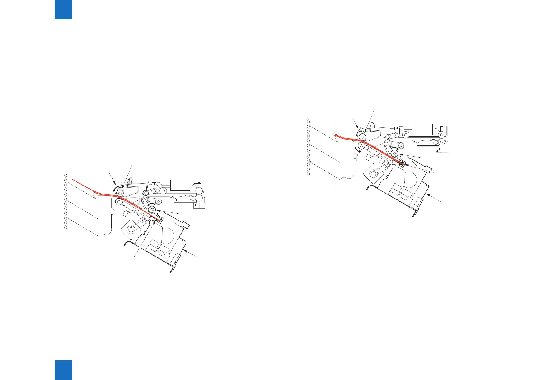
Last Sheet
When alignment of the last sheet completes, the nisher controller PCB moves the aligning
plate to alignment position with the aligning motor (M103/M104) (with the paper held with the
aligning plate).
Then the nisher controller PCB staples at the specied staple position.
After stapling, the nisher controller PCB starts the swing motor (M106) and lowers the swing
guide.
Then the stack is ejected by the stack delivery roller, return roller, and rear end assist guide.
Rear end
assist guide
Return roller
Stapler
Stack ejection roller
Swing guide
F-2-78