4
4
4-22
4-22
Parts Replacement and Cleaning Procedure > Main Units > Removing the Processing Tray
Parts Replacement and Cleaning Procedure > Main Units > Removing the Processing Tray
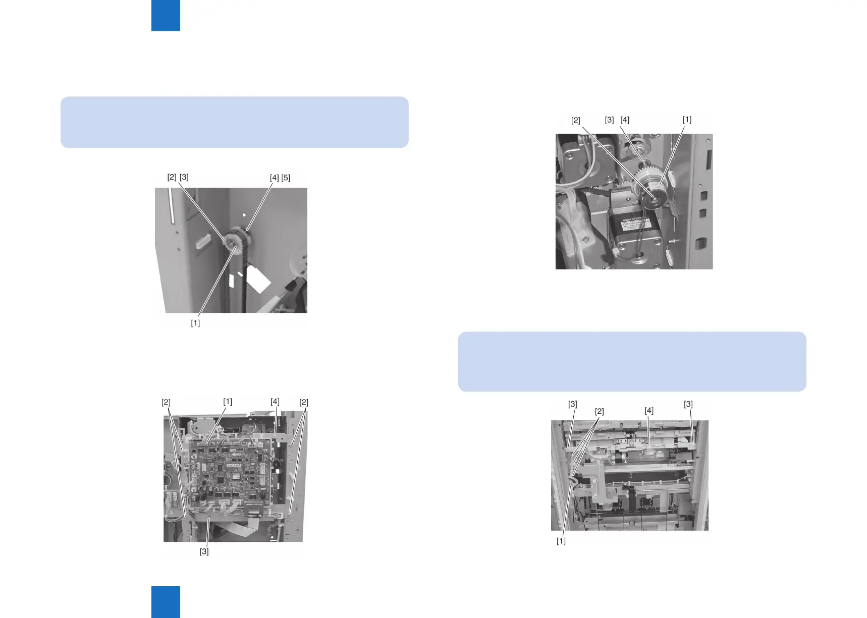
10) Remove the stack delivery roller front side E ring [1], gear [2], parallel pin [3], E ring [4],
and bushing [5].
NOTE:
The parallel pin [3] drops when the gear [2] is removed. Be careful not to loose it.
11) Remove all nisher controller PCB connectors[1].
12) Remove four screws [2]. Remove the screw [3] securing the ground wire and remove the
nisher controller PCB [4].
F-4-38
F-4-39
13) Release the claw [1] of the stack delivery roller rear side clutch [2] and remove the clutch
[2].
14) Remove the E ring [3] and bushing [4] and remove the stack delivery roller.
15) Disconnect the connector [1] and remove harness from the clamp and edge saddle [2].
16) Remove two screws [3] and pull out the processing tray [4] in the paper delivery
direction.
NOTE:
When removing parts inside the processing tray, be careful not to exert force on the
aligning plate (front/rear) or the rear end stopper plate.
F-4-40
F-4-41


 To Next Page