2-4T -296
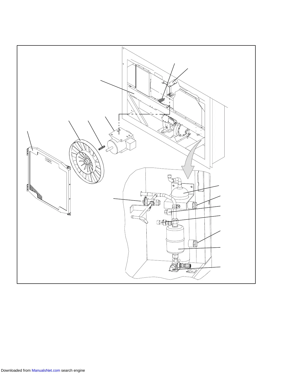
2.1.5 Air Cooled Condenser Section
The air cooled condenser section (Figure 2-4) consists
ofthecondenser fan, condensercoil, receiver withsight
glass/moisture indicator, quench valve, manual liquid
line valve, filter-drier, condenser pressure transducer
and fusible plug.
Thecondenserfanpullsairinthebottomofthecoilandit
isdischargedhorizontallyoutthroughthecondenserfan
grille.
5
6
7
15
1
2
4
3
8
10
9
11
13
12
14
1. Grille and V enturi Assembly
2. Condenser Fan
3. Key
4. Condenser Fan Motor
5. Condenser Coil Cover
6. Condenser Coil
7. Condenser Motor Mounting Bracket
8. Receiver
9. Sight Glass
10. Fusible Plug (Rupture Disc -- Alternate)
11. Condenser Pressure Transducer
12. Sight Glass/Moisture Indicator
13. Filter-Drier
14. Liquid Line Service Valve
15. Quench Valve
Figure 2-4 Condenser Section
Downloaded from ManualsNet.com search engine