T -296
2-1
SECTION 2
DESCRIPTION
2.1 GENERAL DESCRIPTION
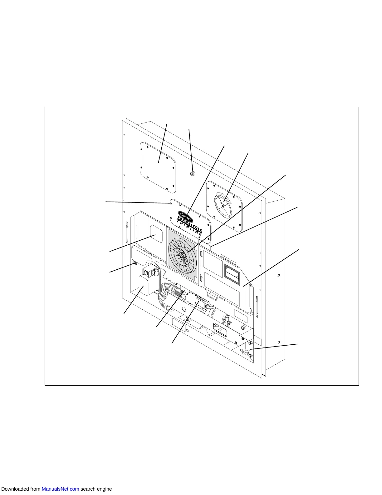
2.1.1 Refrigeration Unit -- Front Section
The unit is designed so that the majority of the
components are accessible from the front, see
Figure 2-1.Theupperaccesspanelsallowentryintothe
evaporator section, and the center access panel allows
access to the thermostatic expansion valve and
evaporator coil heaters. The unit model number, serial
numberandparts identificationnumbercanbefoundon
the serial plate to the left of the compressor.
2.1.2 Fresh Air Makeup Vent
Thefunctionoftheupperairventistoprovideventilation
for commodities that require fresh air circulation.
1
2
3
6
4
9
5
10
12
7
13
11
8
14
1. Access Panel (Evap. Fan #1)
2. Thermometer Port
3. Access Panel (Heater & Thermostatic
Expansion Valve)
4. Upper Fresh Air Makeup Vent and Access
Panel (Evap. Fan #2
5. Condenser Fan
6. Fork Lift Pockets
Unit Serial Number, Model Number and
Parts Identification Number (PID) Plate
7. Control Box
8. Receiver or Water Cooled Condenser
9. Compressor
10. Unit Serial Number, Model Number and
Parts Identification Number (PID) Plate
11. Autotransformer
12. Interrogator Connector (Front right)
13. )Temperature Recorder
14. TIR (Transports Internationaux Routiers)
Sealing Provisions - Typical All Panels
Figure 2-1 Refrigeration Unit -- Front Section
Downloaded from ManualsNet.com search engine