3-3
T -296
812 33 3 3 345 67
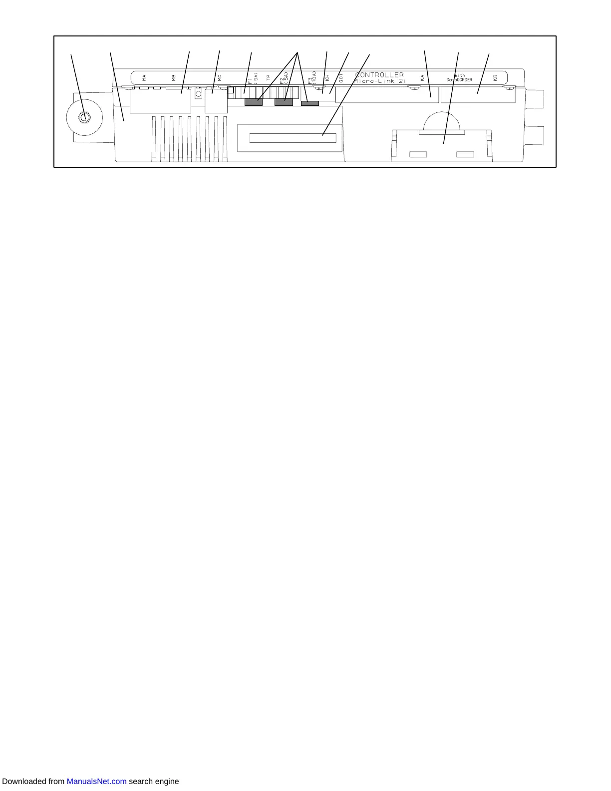
1. Mounting Screw
2. Micro-Link 2i
Controller
3. Connectors
4. Test Points
5. Fuses
6. Control Circuit Power Connection
(Location: In back of controller)
7. Software Programming Port
8. Battery Pack
Figure 3- 4 Micro-Link 2i Controller
3.1.3 Controller
CAUTION
Do not remove wire harnesses from con-
troller unless you are grounded to the unit
frame with a static safe wrist strap.
CAUTION
Unplug all controller wire harness connec-
tors before performing arc welding on any
part of the container.
NOTE
Do not attempt to service the controller. Break-
ing the seal will void the warranty.
The Micro--Link 2i controller is a single module
microprocessor as shown in Figure 3- 4. It is fitted with
test points, harness connectors and a software card
programming port.
3.2 CONTROLLER SOFTWARE
The controller software is a custom designed program
that is subdivided into the Configuration Software and
the Operational Software. The controller software
performs the following functions:
a. Control supply or return air temperature to required
limits, provide modulated refrigeration control, elec-
tric heat control and defrost. Defrost is performed to
clear build up of frost and ice from the coil to ensure
continuous conditioned air delivery to the load.
b. Providedefaultindependentreadoutsofsetpointand
supply or return air temperatures.
c. Provide ability to read and (if applicable) modify the
Configuration Software Variables, Operating Soft-
ware Function Codes and Alarm Code Indications.
d. ProvideaPre-Tripstep-by-stepcheckoutofrefrigera-
tion unit performance including: proper component
operation, electronic and refrigeration control opera-
tion, heater operation, probe calibration, pressure
limiting and current limiting settings.
e. Provide battery powered ability to access or change
selected codes and set point without AC power con-
nected
f. Provide the ability to reprogram the software through
the use of a memory card. The memory card auto-
matically downloads new software to the controller
when inserted.
3.2.1 Configuration Software (Configuration Vari-
ables)
The Configuration Software is a variable listing of the
components available for use by the Operational
Software. This software is factory installed in
accordance with the equipment fitted and options listed
on the original purchase order . Changes to the
Configuration Software are required only when the
originalsoftwarehasbeenlostor aphysicalchangehas
beenmadetotheunit suchastheadditionor removal of
an option. A Configuration Variable list is provided in
Table 3-4 (page 3-13). Change to the factory installed
Configuration Software is achieved via a configuration
card.
3.2.2 Operational Software (Function Codes)
The Operational Software is the actual operation
programming of the controller which activates or
deactivatescomponentsinaccordancewithcurrentunit
operation conditions and operator selected modes of
operation.
The programming is divided into function codes. Some
of the codes are read only while the remaining codes
may be user configured. The value of the user
configurable codes can be assigned in accordance with
user desired mode of operation. A list of the function
codes is provided in Table 3-5 (page 3-14)
To access the function codes, perform the following:
a. Press the CODE SELECT key, then press an arrow
key until the left window displays the desired code
number .
b. The right window will display the value of this item for
five seconds before returning to the normal display
mode.
c. If a longer time is desired, press the ENTER key to
extend the time to 30 seconds.
3.3 MODES OF OPERATION
The Operational Software responds to various inputs.
These inputs come from the temperature and pressure
sensors, the temperature set point, the settings of the
the configuration variables and the function code
Downloaded from ManualsNet.com search engine