T -296 4-6
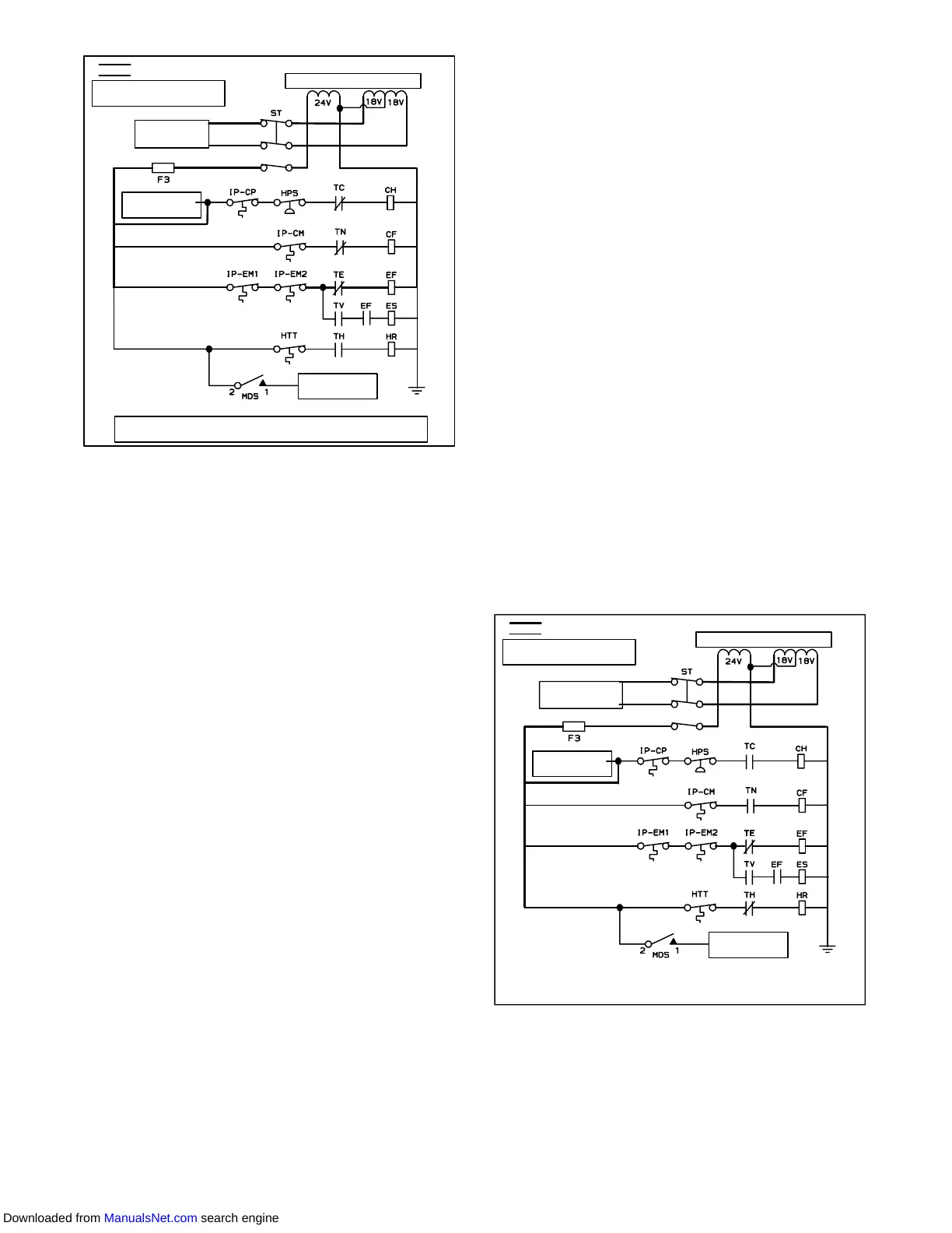
CONTROL TRANSFORMER
POWER TO
CONTROLLER
SIGNAL TO
CONTROLLER
SIGNAL TO
CONTROLLER
ENERGIZED
DE--ENERGIZED
FOR FULL DIAGRAM AND
LEGEND, SEE SECTION 7
NOTE: HIGH SPEED EVAPORATOR FAN SHOWN. FOR LOW SPEED
CONTACT TE IS DE--ENERGIZED AND CONTACT TV IS ENERGIZED
Figure 4-5 Perishable Mode Cooling
4.10.1 Sequence Of operation -- Perishable Mode
Cooling
NOTE
In the Conventional Perishable Mode of opera-
tion theevaporator motors run inhigh speed.In
theEconomy PerishableMode thefan speedis
varied.
NOTE
Inlowtemperatureambients the condenserfan
willbecycled bythe controllerto maintainprop-
er condensing pressure.
a. With supply air temperature above set point and de-
creasing, the unit will be cooling with the condenser
fan motor (CF), compressor motor (CH), evaporator
fan motors (EF) energized and the COOL light illumi-
nated. (See Figure 4-5.)
b. When the air temperature decreases to a predeter-
mined tolerance above set point, the in-range light is
illuminated.
c. As the air temperature continues to fall, modulating
cooling starts at approximately 2.5_C(4.5_F) above
set point. (See Figure 4-3)
d. The controller monitors the supply air. Once the sup-
ply air falls below set point and 0% SMV position is
reached, the controller periodically records the sup-
ply air temperature, set point and time. A calculation
isthenperformedby subtracting thesetpoint reading
from the supply air and multiplying the result by the
time reading. The result is negative number.
e. Whenthe calculation reaches --250, contacts TCand
TN are opened to de-energize compressor and con-
denser fan motors. The cool light is also de-ener-
gized.
f. Theevaporatorfanmotorscontinuetoruntocirculate
air throughout the container. The in-range light re-
mains illuminated as long as the supply air is within
tolerance of set point.
g. When the supply air temperature increases to 0.2_C
(0.4_F) above set point and the three minute off time
has elapsed, relays TC and TN are energizes to re-
start the compressor and condenser fan motors. The
cool light is also illuminated.
4.10.2 Sequence Of Operation --
Perishable Mode Heating
NOTE
The unit will heat only when in the Perishable
Mode, relay TH is electronically locked out
when in the Frozen Mode.
a. Iftheairtemperature decreases0.5_C(0.9_F)below
set point, the system enters the heating mode. (See
Figure 4-3). The controller closes contacts TH (see
Figure 4-6) to allow power flow through the heat ter-
mination thermostat (HTT) to energize the heaters
(HR). The HEAT light is also illuminated. The evapo-
rator fans continue to run to circulate air throughout
the container.
b. When the temperature rises to 0.2_C(0.4_ F) below
set point, contact TH opens to de--energize the heat-
ers. TheHEATlightisalsode--energized.Theevapo-
rator fans continue to run to circulate air throughout
the container.
c. A safety heater termination thermostat (HTT), at-
tached to an evaporator coil support, will open the
heating circuit if overheating occurs.
CONTROL TRANSFORMER
POWER TO
CONTROLLER
SIGNAL TO
CONTROLLER
SIGNAL TO
CONTROLLER
ENERGIZED
DE--ENERGIZED
FOR FULL DIAGRAM AND
LEGEND, SEE SECTION 7
Figure 4-6 Perishable Mode Heating
4.10.3 Sequence Of operation -- Frozen Mode
Cooling
NOTES
1. In the Frozen Mode of operation the
evaporator motors run in low speed.
Downloaded from ManualsNet.com search engine