6-2T -296
5. Front seat both manifold gauge set valves and dis-
connect from cylinder . The gauge set is now ready
for use.
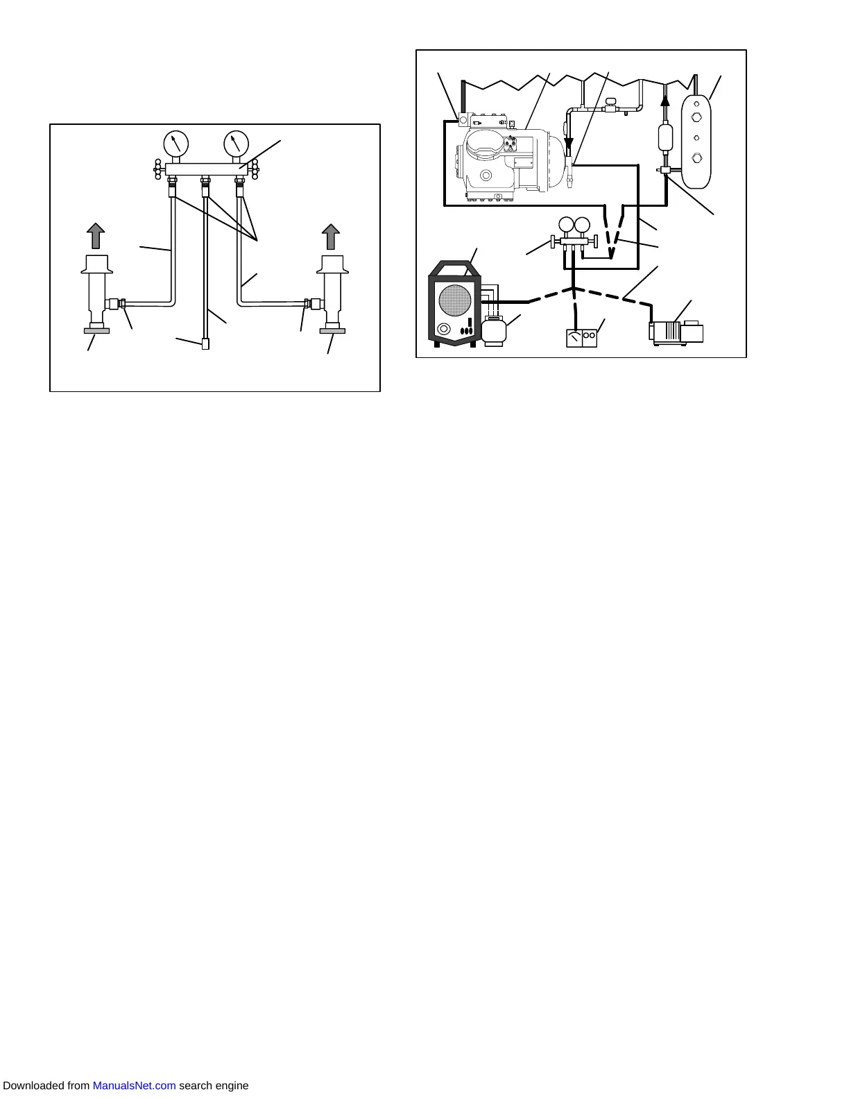
To Low Side
Service Port
To High Side
Service Port
-Red
- Yellow
Blue
Red Knob
Blue Knob
1
2
3
3
3
2
4
5
6
4
1. Manifold Gauge Set
2. Hose Fitting (0.5-16 Acme)
3. Refrigeration and/or Evacuation Hose
. (SAE J2196/R-134a)
4. Hose Fitting w/O-ring (M14 x 1.5)
5. High Side Field Service Coupling
6. Low Side Field Service Coupling
Figure 6-3 R-134a Manifold Gauge/Hose Set
b. Connecting Manifold Gauge/Hose Set
Connection of the manifold gauge/hose set (see
Figure 6-4) is dependent on the component being
serviced. If only the compressor is being serviced, the
highsidecouplingis connectedtothe dischargeservice
valve. Forserviceof the lowside(after pumpdown),the
high side coupling is connected to the liquid line service
valve. The center hose connection is brought to the tool
beingused. Toconnectthemanifoldgauge/hoseset,do
the following.
1. Remove servicevalve stem caps andcheck tomake
sure they are backseated. Remove service port
caps. (See Figure 6-1)
2. Connect the high side field service coupling (see
Figure 6-3) to the discharge or liquid line valve ser-
vice valve port.
3. Turn the high side field service coupling knob (red)
clockwise, which will open the high side of the sys-
tem to the gauge set.
4. Connect the low side field service coupling to the
suction service valve port.
5. Turn the low side field service coupling knob (blue)
clockwise,whichwillopenthelowsideof thesystem
to the gauge set.
6. To read system pressures: slightly midseat the high
side and suction service valves.
6
4
5
7-BLUE
D
S
10
1
2
3
8-YELLOW
9-RED
13
11
12
1. Discharge Service
Valve
2. Compressor
3. Suction Service Valve
4. Receiver or Water
Cooled Condenser
5. Liquid Service Valve
6. Vacuum Pump
7. Low Side Hose
8. Center Hose
9. High Side Hose
10. Electronic Vacuum
Gauge
11. Manifold Gauge Set
12. Refrigerant Cylinder
13. Reclaimer
Figure 6-4. Refrigeration System Service
Connections
CAUTION
To prevent trapping liquid refrigerant in the
manifoldgaugesetbesuresetisbroughtto
suction pressure before disconnecting.
c. Removing the Manifold Gauge Set
1. While the compressor is still ON, backseat the high
side service valve.
2. Midseat both hand valves on the manifold gaugeset
and allow the pressure in the manifold gauge set to
bedrawndowntosuctionpressure. This returnsany
liquidthatmaybeinthehighsidehosetothesystem.
3. Backseat the suction service valve. Backseat both
field service couplings and frontseat both manifold
set valves. Remove the couplings from the service
ports.
4. Install both service valvestem caps and serviceport
caps (finger-tight only).
6.4 PUMPING THE UNIT DOWN
To service the filter-drier, moisture-liquid indicator,
expansion valve, suction modulation valve, quench
valve or evaporator coil, pump the refrigerant into the
high side as follows:
a. Attach manifold gauge set to compressor service
valves. Refer to paragraph 6.3.
b. Start the unit and run in a cooling mode for 10 to 15
minutes.Frontseat the liquid lineservice valve. Place
start-stopswitchintheOFFpositionwhenthesuction
reaches a positive pressure of 0.1 kg/cm@ (1.0 psig).
Downloaded from ManualsNet.com search engine