6-8T -296
1
2
3
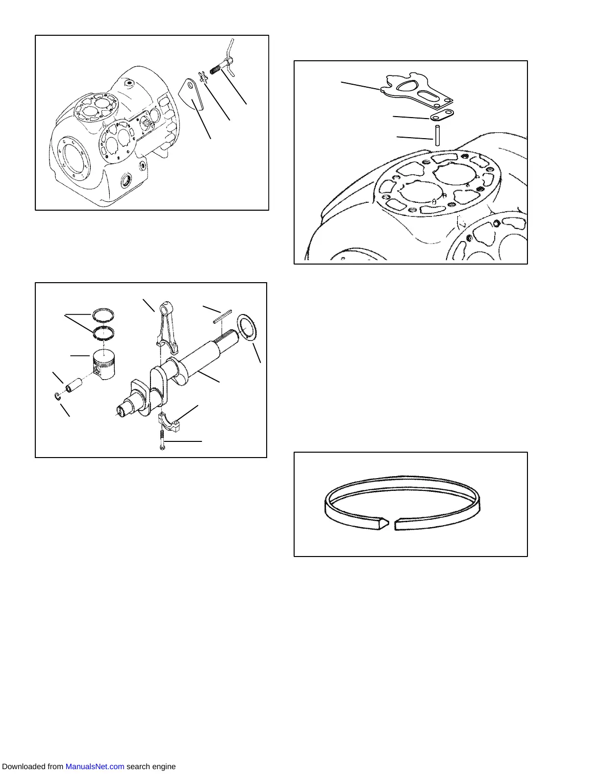
1. Equalizer Tube and
Lock Screw Assembly
2. Lockwasher
3. Counterweight --
Motor End
Figure 6-12 Equalizing Tube and Lock Screw
Assembly
1
2
3
4
5
6
7
8
9
10
1. Capscrew
2. Cap
3. Crankshaft
4. Thrust Washer
5. Rotor Drive Key
6. Connecting Rod
7. Compression Ring
8. Piston
9. Pin
10. Retainer
Figure 6-13 Crankshaft Assembly
6.8.3 Compressor Reassembly
Clean all compressor parts, use a suitable solvent with
proper precautions. Coat all moving parts with the
proper compressor oil before assembly. Refer to
Table 6-8 for applicable compressor torque values.
6.8.4 Preparation
a. Suction and Discharge Valves
If the valve seats look damaged or worn, replace valve
plate assembly. Always use new valves because it is
difficult to reinstall used valves so that they will seat as
before removal. Any valve wear will cause leakage.
1
3
2
1. Suction Valve
2. Suction Valve
Positioning Spring
3. Valve Plate Dowel
Pin
Figure 6-14 Suction Valve & Positioning Springs
Suctionvalves are positionedby dowelpins (seeFigure
Figure 6-14). Do not omit the suction valve positioning
springs. Place the springs so that theends bear against
the cylinder deck (middle bowed away from cylinder
deck). Use new gaskets when reinstalling valve plates
and cylinder heads.
b. Compression Rings
The compression ring is chamfered on the inside
circumference. This ring is installed with the chamfer
toward the top. Stagger the ring end gaps so they are
not aligned.
Figure 6-15 Piston Ring
The gap between the ends of the piston rings can be
checkedwithafeelergaugebyinsertingtheringintothe
piston bore approximately one inch below the top of the
bore. Square the ring in the bore by pushing it slightly
with a piston. The maximum and minimum allowable
ringgapsare0.33and0.127mm(0.013and0.005inch)
respectively.
Downloaded from ManualsNet.com search engine