T -296
4-7
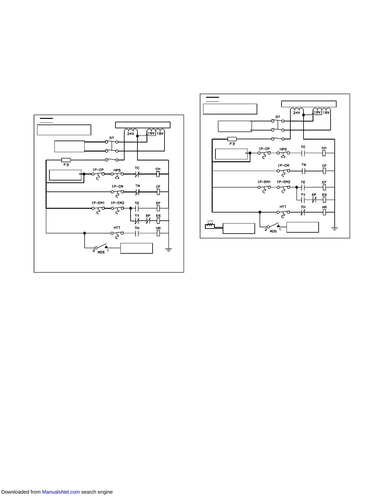
2. In low temperature ambients the
condenser fan will be cycled by the
controller to maintain proper condensing
pressure.
a. With supply air temperature above set point and de-
creasing, the unit will be cooling with the condenser
fan motor (CF), compressor motor (CH), evaporator
fan motors (ES) energized and the COOL light illumi-
nated. (See Figure 4-7.)
b.When the air temperature decreases to a predeter-
mined tolerance above set point, the in-range light is
illuminated.
CONTROL TRANSFORMER
POWER TO
CONTROLLER
SIGNAL TO
CONTROLLER
SIGNAL TO
CONTROLLER
ENERGIZED
DE--ENERGIZED
FOR FULL DIAGRAM AND
LEGEND, SEE SECTION 7
Figure 4-7 Frozen Mode
c. Contacts TC and TN are opened to de-energize the
compressor and condenser fan motors when the re-
turn air temperature decreases to 0.2_C(0.4_F) be-
low set point. The cool light is also de-energized.
d. Theevaporatorfanmotorscontinuetoruntocirculate
air throughout the container. The in-range light re-
mainsilluminatedaslongas thereturnairiswithintol-
erance of set point.
e. When the return air temperature increases to 0.2_C
(0.4_F) above set point and the three minute off time
has elapsed, relays TC and TN are energizes to re-
start the compressor and condenser fan motors. The
cool light is also illuminated.
4.10.4 Sequence Of Operation -- Defrost
The defrost cycle may consist of up to three distinct
operations. The first is de-icing of the coil, the second is
a probe check cycle and the third is snap freeze.
Defrost may be requested by any one of the following
methods:
1. The manual defrost switch (MDS) is closed by the
user .
2. The user sends a defrost request by communica-
tions.
3. The defrost interval timer (controller function code
Cd27) reaches the defrost interval set by the user .
4. Thecontrollerprobediagnosticlogic determinesthat
a probe check is necessary based on the tempera-
ture values currently reported by the supply and re-
turn probes.
5. The controller Demand Defrost configuration vari-
able (CnF40) is set to “In” and the unit has been in
pulldownoperationfor over2.5hours withoutreach-
ing set point.
CONTROL TRANSFORMER
POWER TO
CONTROLLER
SIGNAL TO
CONTROLLER
SIGNAL TO
CONTROLLER
ENERGIZED
DE--ENERGIZED
FOR FULL DIAGRAM AND
LEGEND, SEE SECTION 7
SIGNAL TO
CONTROLLER
Figure 4-8 Defrost
Processing of a defrost request is controlled by the
Defrost Termination Thermostat. The Defrost
Termination Thermostat is not a physical component. It
is a software point that acts as a thermostat, allowing
defrost when it is considered “closed” and preventingor
terminating defrost when it is considered “open”. The
actual temperatures used to make the “open” or
“closed” determinations are dependent on the type of
defrost request made and the operator setting of
configuration variable CnF41. Configuration variable
CnF41may be factory set at the default value of
25.6°C(78°F) or a lower value of 18°C(64°F).
When a request for defrost is made by the use of the
Manual Defrost Switch or Communications, the unit will
enter defrost when the reading at the Defrost
Temperature Sensor is at or below the CnF41 setting.
Defrost will terminate when the Defrost Sensor
Temperature reading rises above the CnF41 setting.
When a request for defrost is madeby probe check, the
unit will enter defrost when the Defrost Temperature
Sensorreadingisatorbelow25.6°C(78°F).Theunitwill
terminate defrost when the Defrost Temperature
Sensor reading rises above 25.6°C(78°F)
Whenarequest for defrost is made bydemand defrost,
theunitwillenterdefrostwhenthereadingattheDefrost
Temperature Sensor is at or below 18°C (64.4°F).
Defrost will terminate when the Defrost Sensor
Temperature reading rises above the CnF41 setting.
When a defrost has terminated, the defrost interval
timerwillbegincountingwhenthereadingat theDefrost
Temperature Sensor is at or below 10°C(50°F). Once
the timer has counted the required time, the unit will
Downloaded from ManualsNet.com search engine