2-6T -296
2.1.7 Control Box Section
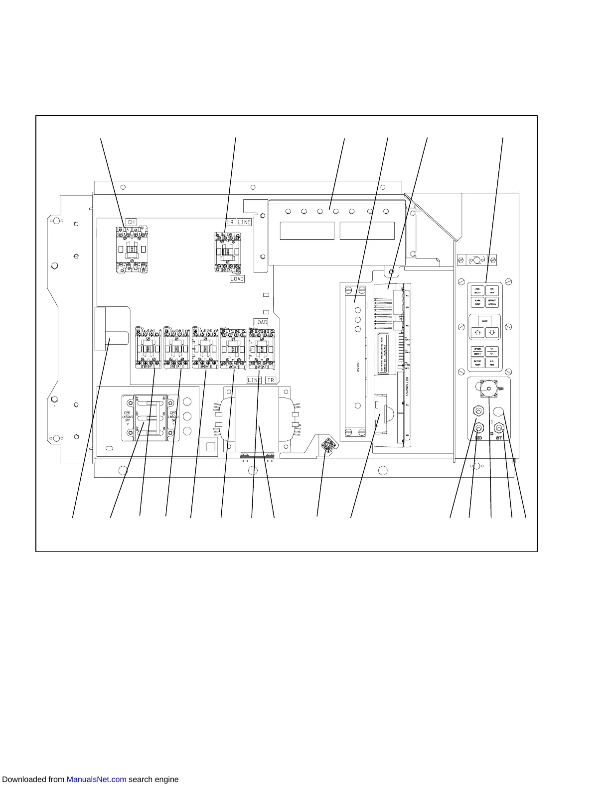
The control box (Figure 2-6) includes the manual
operationswitches; circuit breaker (CB-1); compressor,
fan and heater contactors; control power transformer;
fuses; key pad; display module; current sensormodule;
controller module and the communications interface
module.
2.1.8 Communications Interface Module
The communications interface module is a slave
module which allow communication with a master
central monitoring station. The module will respond to
communication and return information over the main
powerline.Refertothemastersystemtechnicalmanual
for further information.
161718 121415
12
3
4
5
6
7
10 919
11 813
20
21
1. Compressor Contactor
2. Heater Contactor
3. Display Module
4. Communications Interface Module
5. Controller/DataCORDER Module (Controller)
6. Key Pad
7. Emergency Defrost Light
8. Start-Stop Switch
9. Remote Monitoring Receptacle
10. Manual Defrost Switch
11. Condenser Fan Switch
12. Controller Battery Pack
13. Interrogator Connector (Box Location)
14. Control Transformer
15. Evaporator Fan Contactor - E1
16. Evaporator Fan Contactor - S1
17. Evaporator Fan Contactor - S2 or EF
18. Evaporator Fan Contactor - E2 or ES
19. Condenser Fan Contactor
20. Circuit Breaker -- 460V
21. Current Sensor Module
Figure 2-6 Control Box Section
Downloaded from ManualsNet.com search engine