6-27
T -296
1
2
3
4
5
6
7
8
9
10
11
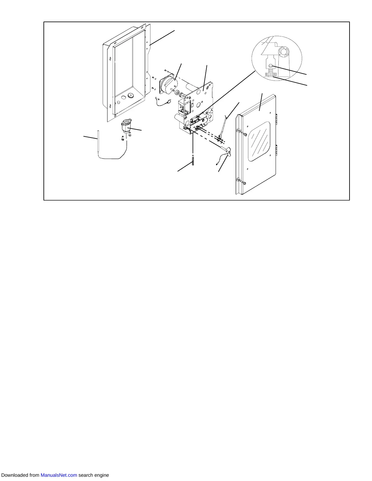
1. Mechanical Temperature
Recorder Bulb
2. Element
3. Recorder Box
4. 31 Day Clock
5. Mechanism and Platen Assembly
6. Set Screw
7. Pinion Shaft
8. Recorder Door
9. Stylus
10. Clock Winding Key
11. Push Rod
Figure 6-32. Partlow Mechanical Temperature Recorder
6.24 SAGINOMIYA TEMPERATURE RECORDER
NOTE
Do not overtighten chart nut after replacing
chart.
6.24.1Battery Check
a. Open door and remove chart nut and platen.
b. Push voltage indicator test switch (item 3,
Figure 6-33). Replace battery if voltage indicator
points to the red or white zone.
6.24.2Calibration
NOTES
1 One full turn with the adjustment screw
changes the indicated temperature by
approximately 5°C(9°F).
2 Overtightening of setscrew may change
set temperature.
3 Calibration should only be done when
sensor temperature is decreasing.
4 DO NOT move stylus by hand.
a. Install new chart on platen.
b. Place the recording thermometer sensing bulb in
0°C(32°F) ice-water bath. Ice-water bath is
prepared by filling an insulated container (of
sufficient size to completely immerse bulb) with ice
cubes or chipped ice, filling voids between ice with
water, and agitating until mixture reaches 0°C
(32°F) as shown by a laboratory thermometer.
c. Whentheicebathtemperaturereaches0°C(32°F),
as shown by the laboratory thermometer reading,
compare the temperature indicated by stylus with
temperature shown by the thermometer. Allow
sufficient time to ensure bulb has cooled to the ice
bath temperature. If the two readings do not agree
within+/--0.3°C(1/2°F),therecordingthermometer
should be rezeroed. Do not touch stylus during the
checkout procedure.
d. If adjustment is required, loosen setscrew
(cross-recessed head). Using a 7 mm wrench,
rotate the adjustment screw clockwise to set the
stylus 1 to 2°C(1.8to3.6°F) higher than desired
temperature.
e. Rotate the adjustment screw counterclockwise to
set the stylus about 0.5°C(0.9°F) higher than set
Downloaded from ManualsNet.com search engine