6-21
T -296
mixture reaches 0_C(32_F) measured on a labora-
tory thermometer.
b. Start unit and check sensor reading on the control
panel.The readingshould be 0_C(32_F). If theread-
ingiscorrect,reinstallsensor; ifit isnot,continuewith
the following.
c. Turn unit OFF and disconnect power supply.
d. Refertoparagraph6.20andremovecontrollertogain
access to the sensor plugs.
e. Using the plug connector marked “EC”, that is con-
nected to the back of the controller,locate the sensor
wires (RRS, RTS, SRS, STS, AMBS, DTS, CPDS
ORCPSSasrequired).Followthosewirestothecon-
nector and using the pins of the plug, measure the
resistance. Values are provided in Table 6-1.
Table 6-1 Sensor Temperature/Resistance Chart
Temperature
Centigrade
Temperature
Fahrenheit
Resistance
(Ohms)
RRS, RTS, SRS and STS:
0 32 32,650±91
25 77 10,000±50
AMBS and DTS
0 32
32,650 + 1720
-- 1620
25 77
10,000 + 450
-- 430
Duetothevariations and inaccuraciesinohmmeters,
thermometers or other test equipment, a reading
within 2% of the chart value would indicate a good
sensor. If a sensor is defective, the resistance read-
ingwillusually bemuchhigheror lowerthantheresis-
tance values given.
6.21.2 Sensor Replacement
a. Turn unit power OFF and disconnect power supply.
b. For two wire sensors, cut cable 5 cm (2 inches) from
shoulder of defective sensor and discard the defec-
tive sensor only. For three wire sensors cut at 23 cm
(9 inches). Slide the cap and grommet off well
mountedsensor and save for possible reuse. Donot
cut the grommet.
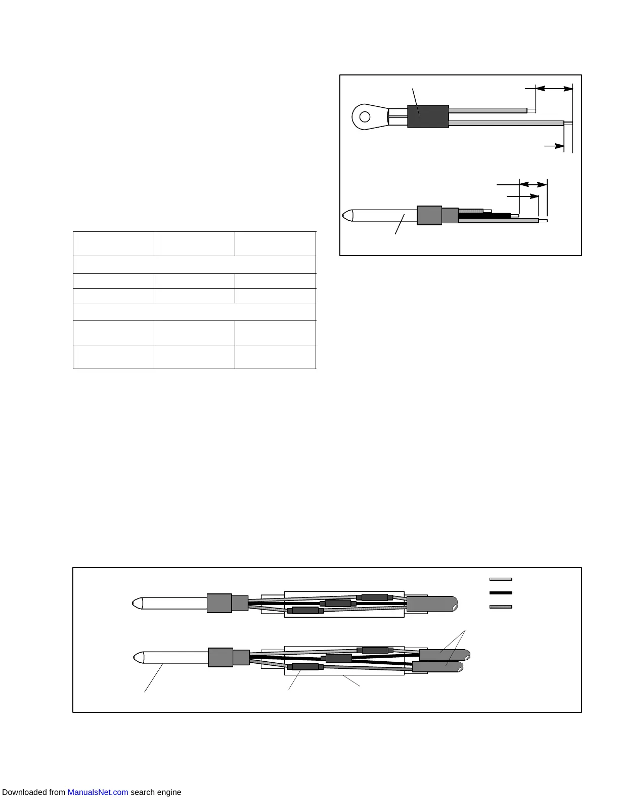
c. If required, prepare the replacement sensor by cut-
tingsensorwire(s)back40mm (1-1/2inch).Forthree
wire sensors the black wire should be cut at the
middlelengthandthered/whitewirecuttotheshorter
length. (See Figure 6-27.)
Sensor
40 mm (1 1/2 inch)
6.3 mm (1/4 inch)
Mounting Stud Type
Sensor
40 mm (1-1/2 inches)
6.3 mm (1/4 inch)
Bulb Type
Figure 6-27 Sensor Types
d. Prepare the cables by cutting wires to the oppositeof
the sensor. (See Figure 6-28.)
When installing a single wire color two wire sensor,
cut one wire of existing two wire cable 40 mm (1-1/2
inch) shorter than the other wire.
When replacing two single sensors with a combina-
tion (three wire) sensor , the black wires of the cables
should be cut to the same length and the red wire of
one cable cut to the shorter length.
When replacing a original three wire sensor, cut the
black wireto the middle length and the red wire tothe
shorter length.
e. Strip back insulation on all wiring 6.3 mm (1/4 inch).
f. Slide a large piece of heat shrink tubing over the
cable, and place small pieces of heat shrink tubing,
one over each wire, before adding crimp fittings as
shown in Figure 6-28.
g. Ifrequired,slidethecap andgrommet assemblyonto
the replacement sensor. If the replacement sensor is
ofalargerdiameterthantheoriginal,adifferentgrom-
met may be required.
h. Slip crimp fittings over dressed wires (keeping wire
colors together). Make sure wires are pushed into
crimpfittings as far as possible and crimp withcrimp-
ing tool.
Sensor (Typical)
Cable
Heat Shrink
T ubing
Large Heat Shrink
T ubing
REPLACEMENT 2 WIRE TO 2
WIRE OR 3 WIRE TO 3 WIRE
REPLACEMENT FOR DUAL SINGLE
SENSOR CONFIGURATION
RED
BLACK
RED/WHITE
Figure 6-28 Sensor and Cable Splice
i. Solder spliced wires with a 60% tin and 40% lead
Rosincore solder .
j. Slide heat shrink tubing over splice so that ends of
tubing cover both ends of crimp as shown in
Figure 6-28.
Downloaded from ManualsNet.com search engine