3-8T -296
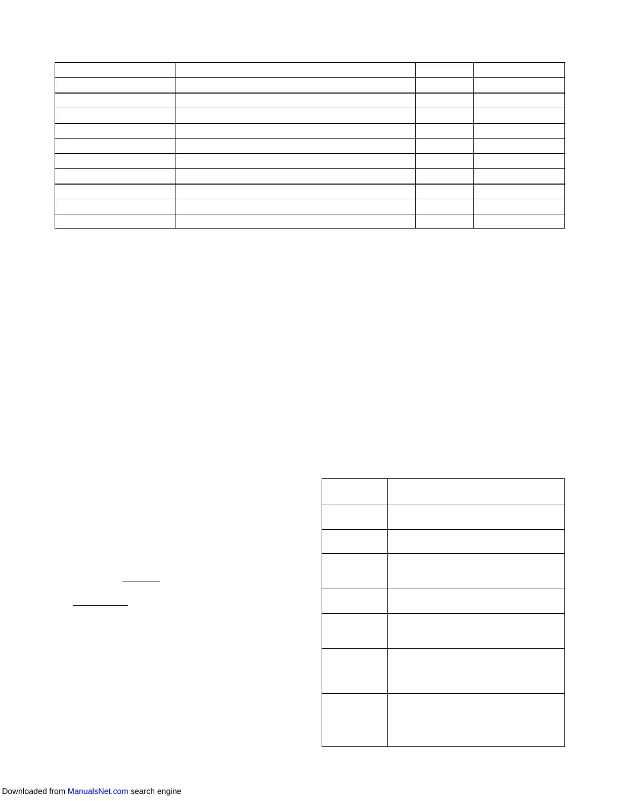
Table 3 -2 DataCORDER Configuration Variables
CONFIGURATION NO.
TITLE DEFAULT OPTION
dCF01 (Future Use) -- -- -- --
dCF02 Sensor Configuration 2 2,5,6,9,54,64,94
dCF03 Logging Interval (Minutes) 60 15,30,60,120
dCF04 Thermistor Format Short Low , Normal
dCF05 Thermistor Sampling Type A A,b,C
dCF06 Controlled Atmosphere/Humidity Sampling T ype A A,b
dCF07 Alarm Configuration USDA Sensor 1 A Auto, On, Off
dCF08 Alarm Configuration USDA Sensor 2 A Auto, On, Off
dCF09 Alarm Configuration USDA Sensor 3 A Auto, On, Off
dCF10 Alarm Configuration Cargo Sensor A Auto, On, Off
b. Configuration Software
The configuration software controls the recording and
alarm functions of the DataCORDER. Reprogramming
to the factory installed configuration is achieved via the
same configuration card as the unit control module
software. Changes to the software may be made made
using the Data View integration device. A listing of the
configuration variables is provided in Table 3-2.
Descriptions of DataCORDER operation for each
variable setting are provided in the following
paragraphs.
3.6.3 Sensor Configuration (dCF02)
T wo modes of operation may be configured, the
Standard Mode and the Generic Mode.
a. Standard Mode
In the standard mode, the user may configure the
DataCORDER to record data using one of seven
standard configurations. The seven standard
configuration variables, with their descriptions, are
listedinTable3-3.
The six thermistor inputs (supply, return, USDA #1, #2,
#3 and cargo probe) and the humidity sensor input will
be generated by the DataCORDER. An example of a
report using a standard configuration is shown in
Figure 3- 5.
NOTE
The DataCORDER software uses the supply
and return recorder
sensors. The temperature
control software uses the supply and return
temperature
sensors.
b. Generic Mode
Thegenericrecordingmodeallows userselectionofthe
networkdatapointstoberecorded.Theuser mayselect
uptoatotalofeightdatapoints forrecording. Alist ofthe
datapointsavailableforrecordingfollows.Changingthe
configuration to generic and selectingwhich datapoints
torecordmaybedoneusingtheCarrierTransicoldData
Retrieval Program.
1. Control mode
2. Control temperature
3. Frequency
4. Humidity
5. Phase A current
6. Phase B current
7. Phase C current
8. Main voltage
9. Suction modulation valve percentage
10. Discrete outputs (Bit mapped -- require special
handling if used)
11. Discrete inputs (Bit mapped -- require special
handling if used)
12. Ambient sensor
13. Compressor suction sensor
14. Compressor discharge sensor
15. Return temperature sensor
16. Supply temperature sensor
17 Defrost temperature sensor
18. Discharge pressure transducer
19. Suction pressure transducer
20. Condenser pressure transducer
Table 3 -3 DataCORDER Standard Configurations
Standard
Config.
Description
2 sensors
(dCF02=2)
2 thermistor inputs(supply & return)
5 sensors
(dCF02=5)
2 thermistor inputs(supply & return)
3 USDA thermistor inputs
6 sensors
(dCF02=6)
2 thermistor inputs(supply & return)
3 USDA thermistor inputs
1 humidity input
9 sensors
(dCF02=9)
Not Applicable
6 sensors
(dCF02=54)
2 thermistor inputs(supply & return)
3 USDA thermistor inputs
1 cargo probe (thermistor input)
7 sensors
(dCF02=64)
2 thermistor inputs(supply & return)
3 USDA thermistor inputs
1 humidity input
1 cargo probe (thermistor input)
10 sensors
(dCF02=94)
2 thermistor inputs(supply & return)
3 USDA thermistor inputs
1 humidity input
1 cargo probe (thermistor input)
3 C.A. inputs (NOT APPLICABLE)
Downloaded from ManualsNet.com search engine