6-18T -296
the suction gauge. Within one minute the suction
pressure will go into a vacuum. This is an indication
that the valve is moving.
4. If no change in suction pressure is detected, check
for resistance (refer to step 6.18.2), and check con-
nections for proper continuity and retest. If the valve
is functioning and all connections and motor resist-
ance are good, check the drive module. (Refer to
step 6.18.3)
5. If the valve is determined as faulty after completing
theabovesteps,performalowsidepumpdown.Re-
movevalvepowerheadassembly,andreplacewitha
NEW valvepowerheadassembly,torquenutto35ft-
lb, evacuate low side, and open all service valves.
CAUTION
DONOTdisassemblepistonfromNEWsuc-
tion modulating valve powerhead assem-
bly. Doing so may result in damage to pis-
ton.
6.18.3 Checking The Drive Module
a. Turn unit OFF.
b. Disconnect the four pin connector to the SMV.
c. Withvoltmetersettoread24voltsAC,attachthepos-
itiveleadtothedrivemoduleoutletpin“A”(wire 1A)of
thefourpinconnectorandthenegativeleadto the“B”
pin(wire1B).
d. Turn ON unit, and watch the volt meter. After a short
delay, the reading should rise to approximately 12
volts.
e. Repeat for pins “C” and “D” (wires 2 A and 2 B).
f. If only one set of pins reads a voltage, check connec-
tions and retest.
g. If the retest reads out the same, the drive module or
controller is faulty.
h. Ifnovoltageispresentinanystep,theoutputfromthe
controller to the drive module may be faulty, and will
require checking the connections and wires from the
controller to the drive module. Refer to step 6.18.4
i. To replace the drive module, disconnect all connec-
tors, unscrew from mounting, and replace with a
NEW drive module in reverse order.
6.18.4 Checking The Controller
a. Turn the unit OFF.
b. Disconnectthesix pinconnectortothe stepper drive
from the controller .
c. Withthe voltmeter setto read50voltsDC, attachthe
positiveleadto outlet pin“A”of thesix pinconnector ,
and the negative lead to pin “B” or TP-9 of the con-
troller.
d. TurnONthe unit for 40 seconds, and watch the volt-
meter. Thereshould be approximately 24 to 32 VDC
shownonpin“A”.
e. There should be zero volts on pin “B”.
f. Afterashortdelay,thereadingshouldrisetoapprox-
imately 24 to 32 VDC on pin “E”.
g. Pins “C” and “D” will have zero to 5 volts transistor
logic (TTL) signals present, however, this can only
be checked with the connector assembled as this is
an open collector type circuit.
By checking the outputs on “A,” “B,” and “E” it can be
verifiedthatthecontroller issupplyingpowertothedrive
module. To be thorough, and if it is desired, the signals
on pins “C” and “D” can be checked as follows:
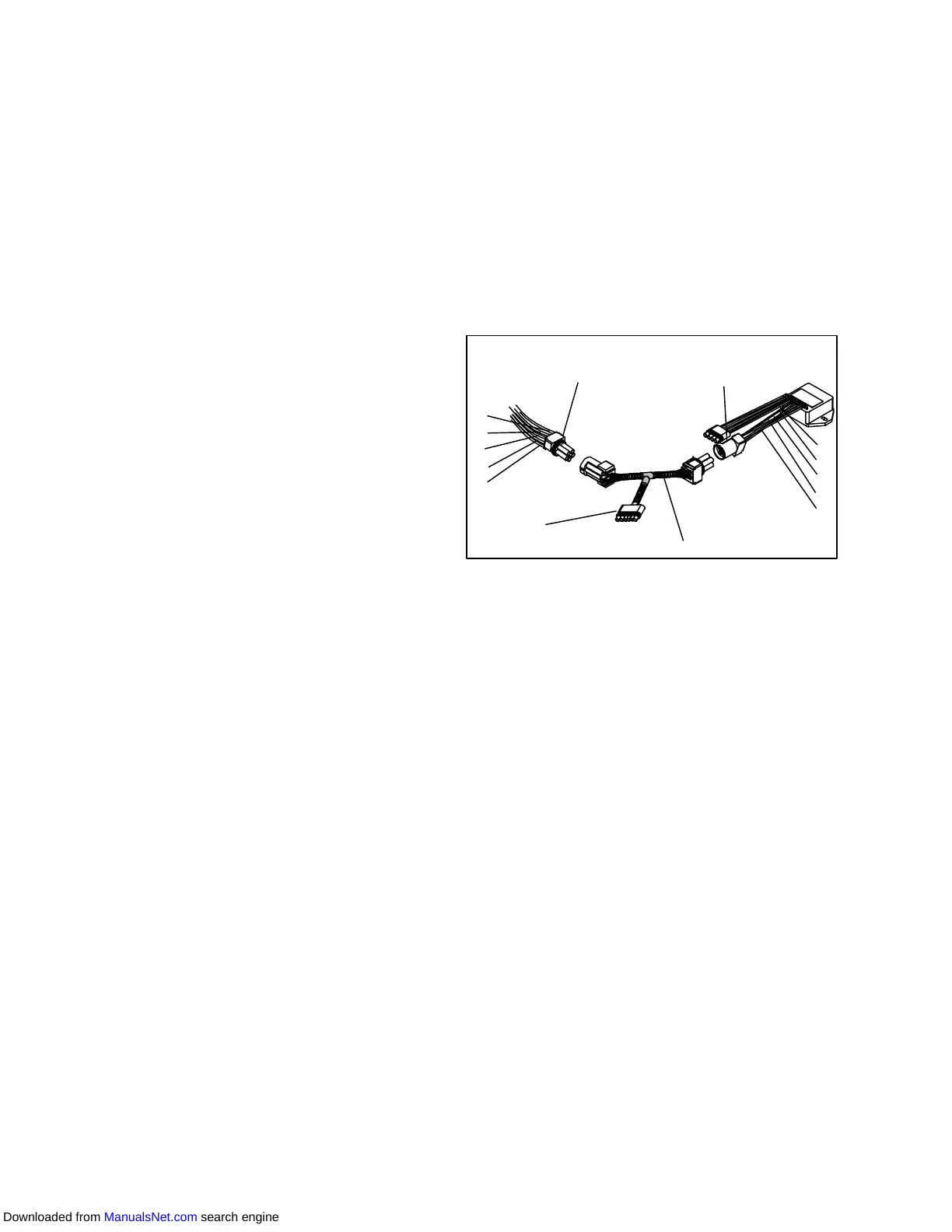
1. Install a jumper assembly (Carrier part number
07--00408--00) toconnect the drivemodule andcon-
troller connectors as shown in Figure Figure 6-25.
2. Connect the positive lead of the voltmeter to test
connector socket “C” and negative lead to socket
“B,” and run as before by resetting unit.
3. Repeat for sockets “D” and “B.”
A
B
C
D
E
A
B
C
D
E
Controller
Connector (EC)
Drive Module
Connector (SD)
Jumper
Test
Connector
Figure 6-25 Jumper Assembly
Thereshouldbeapproximately fivevoltsDC onsockets
“C”and“D”(S1andS2)whenmeasuredasabove. Ifnot
the connections or controller is faulty.
If any of these pins are not consistent, the connections
or controller is suspect. Check and replace as required.
6.18.5 Emergency Repair Procedures:
In the event that the SMV system has a failure and
replacement components are not readily available the
systemcanbeby--passedbyremovingthevalvepiston.
to remove the piston, do the following:
a. Perform a low side pump down. Refer to paragraph
6.4.
b. Remove SMV powerhead by loosening the 2-1/8
inch diameter nut (see Figure 6-24) to relieve any
pressure and then , sliding the powerhead out.
c. Removethepiston byloosening theAllen screwand
removing the piston and screw.
d. Install thepowerhead assembly(without thepiston),
torque to 35 to 40 foot-lbs.
e. Open all valves.
f. Start the unit.
g. Adjust the suction service valve so that the approxi-
mate temperature OR current limit is maintained.
For perishable loads, it is recommendedthat thead-
justment be made so that the available capacity is
slightly larger than the load, the unit will cycle OFF
and ON.
h. Once repair parts become available, repair as re-
quired.
Downloaded from ManualsNet.com search engine