3-2T -296
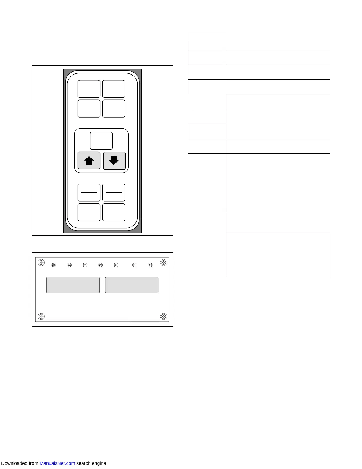
3.1.1 Key Pad
The key pad (Figure 3- 2) is mounted on the right-hand
side of the control box. The key pad consists of eleven
push button switches that act as the user’ s interface
with the controller. Descriptions of the switch functions
are provided in Table 3-1.
ENTER
BATTERY
POWER
DEFROST
INTERVAL
CODE
SELECT
PRE
TRIP
ALARM
LIST
ALT.
MODE
RETURN
SUPPLY
_C
_F
Figure 3- 2 Ke y Pad
COOL HEAT DEFROST IN RANGEALARM SUPPLY RETURN
SETPOINT/Code AIR TEMPERATURE/Data
Figure 3- 3 Display Module
3.1.2 Display Module
The display module (Figure 3- 3) consists of two
backlighted five digit LCD displays and seven indicator
lights. The indicator lights include:
1. Cool -- White LED: Energized when the refrigerant
compressor is energized.
2. Heat -- OrangeLED:Energizedtoindicateheaterop-
eration in the heat or defrost mode.
3. Defrost -- OrangeLED: Energizedwhen theunit is in
the defrost mode.
4. In-Range -- Green LED: Ene rgiz ed wh en the con-
trolledtempera t ureprobeiswithinspecifiedtolerance
of set point.
Table 3 -1 Key Pad Function
KEY
FUNCTION
Code Select Accesses function codes.
Pre-Trip
Displays the pre-trip selection menu.
Discontinues pre-trip in progress.
Alarm List
Displays alarm list and clears the
alarm queue .
Defrost
Interval
Displays selected defrost interval.
Enter
Confirms a selection or saves a
selection to the controller
Arrow Up
Change or scroll a selection upward
Pre-trip advance or test interruption.
Arrow Down
Change or scroll a selection down-
ward. Pre-trip repeat backward
Return/
Supply
Displays non-controlling probe tem-
perature (momentary display).
_C/_F
Displays alternate English/Metric
scale (momentary display). When set
to _F, pressure is displayed in psig
and vacuum in “/hg. “P” appears after
the value to indicate psig and “i” ap-
pears for inches of mercury.
When set to _C. pressure readings
are in bars. “b” appears after the val-
ue to indicate bars.
Battery
Power
Initiate battery backup mode to allow
set point and function code selection
if AC power is not connected.
ALT. Mode
This key is pressed to switch the
functions from the temperature soft-
ware to the DataCORDER Software.
The remaining keys function the
same as described above except the
readings or changes are made to the
DataCORDER programming.
NOTE
The controlling probe in the perishable range
willbetheSUPPLYairprobeandthecontrolling
probe in the frozen range will be the RETURN
air probe.
5. Supply -- Yellow LED: Energized whenthe supplyair
probeisusedforcontrol. WhenthisLEDisilluminated,
thetemperaturedisplayedintheAIRTEMPERA TURE
display is the reading at thesupply airprobe. ThisLED
will flash if dehumidification or humidification is en-
abled.
6. Return -- Yellow LED: Energized when the return air
probeisusedforcontrol. WhenthisLEDisilluminated,
thetemperaturedisplayedintheAIRTEMPERA TURE
display is the reading at the return air probe. This LED
will flash if dehumidification or humidification is en-
abled.
7. Alarm -- RedLED:Energizedwhenthereis an active
or an inactive shutdown alarm in the alarm queue.
Downloaded from ManualsNet.com search engine