6-13
T -296
The valve functions are:
1. Automaticcontrolof therefrigerant flowto matchthe
evaporator load.
2. Prevention of liquid refrigerant entering the com-
pressor.
Unless the valve is defective, it seldom requires
maintenance other than periodic inspection to ensure
that thethermalbulbistightly securedtothesuctionline
and wrapped with insulating compound. (See
Figure 6-19.)Onunitsfittedwithasemi--hermeticvalve,
check to be sure the excess capillary is secured to the
power head assembly and wrapped with insulating
compound.
1
2
3
4
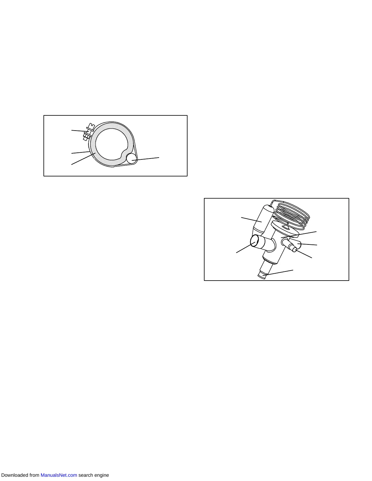
1. Suction Line
2. TXV Bulb Clamp
3. Nut and Bolt
4. TXV Bulb
Figure 6-19 Thermostatic Expansion V alve Bulb
6.14.1 Checking Superheat.
NOTE
Proper superheat measurement should be
completed at --18_C(0_F) container box tem-
perature where possible.
a. Open theheater accesspanel (seeFigure 2-1) toex-
pose the expansion valve .
b. Attach a temperature sensor near the expansion
valve bulb and insulate. Make sure the suction line is
clean and that firm contact is made with the sensor.
c. Connect anaccurate gauge to theservice port direct-
ly upstream of the suction modulating valve
d. Setthetemperatureset pointto --18_C(0_F), andrun
unit until conditions stabilize.
e. The readings may cycle from a high toa low reading.
Take readings of temperature and pressure every
three to five minutes for a total of 5or 6 readings
f. Fromthetemperature/pressurechart (Table 6-9),de-
termine the saturation temperature corresponding to
the evaporator outlet test pressures at the suction
modulation valve.
g. Subtract the saturation temperatures determined in
step f. from the temperatures measured in step e..
The difference is the superheat of the suction gas.
Determine the average superheat It should be 4.5 to
6.7 °C(8to12°F)
6.14.2 Hermetic V alve Replacement
a. Removing the Expansion Valve
NOTES
1. The TXV is a hermetic valve and does not
have adjustable superheat.
2. All connections on the hermetic TXV are
bi--metallic, copper on the inside and
stainless on the outside.
3. All joints on the hermetic TXV (inlet, outlet
and equalizer lines) are brazed.
4. Bi--metallic connections heat up very
quickly.
1
6
5
4
3
2
1. Hermetic Thermostatic Expansion Valve
2. Non-adjustable Superheat Stem
3. Equalizer Connection
4. Inlet Connection
5. Outlet Connection
6. Hermetic Expansion Valve Bulb
Figure 6-20 Hermetic Thermostatic Expansion
Valve
1. Pump down the unit per paragraph 6.4.
Downloaded from ManualsNet.com search engine