6-4T -296
6
45
7
DS
10
1
23
8
9
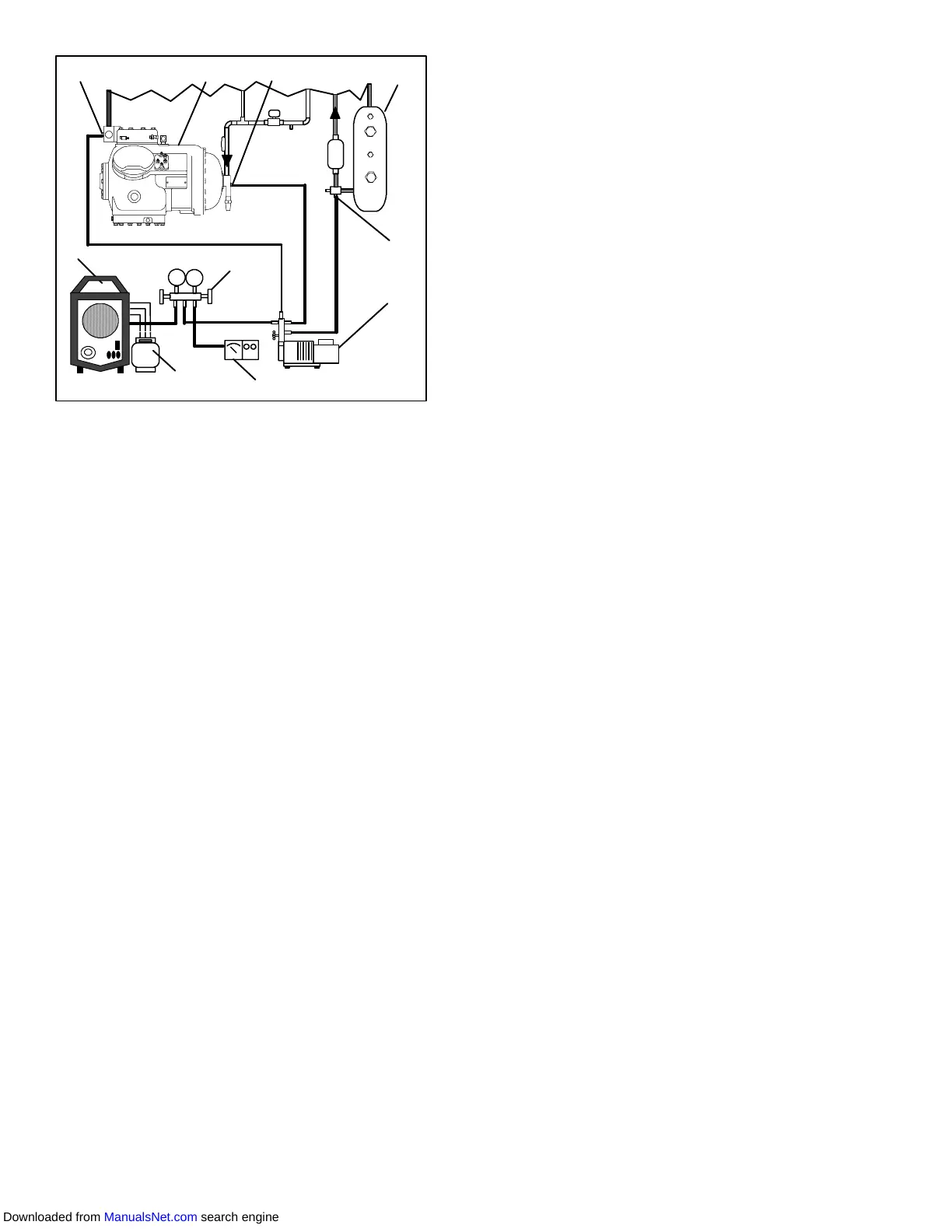
1. Reclaimer
2. Discharge Service
Valve
3. Compressor
4. Suction Service Valve
5. Receiver or Water
Cooled Condenser
6. Liquid Service Valve
7. Vacuum Pump
8. Electronic Vacuum
Gauge
9. Manifold Gauge Set
10. Refrigerant Cylinder
Figure 6-5. Compressor Service Connections
i. Removethe coppertubingandchangethefilter-drier.
Evacuate unit to 500 microns. Close the electronic
vacuumgaugeandvacuumpumpvalves.Shutoffthe
vacuum pump. Wait five minutes to see if vacuum
holds. This procedure checks for residual moisture
and/or leaks.
j. With a vacuum still in the unit, the refrigerant charge
maybe drawn intothe system from arefrigerant con-
tainer on weight scales. Continue to paragraph 6.7
6.6.4 Procedure - Partial System
a. If the refrigerant charge has been removed from the
compressor for service, evacuate only the compres-
sor by connecting the evacuation set--up at the com-
pressor service valves. Follow evacuation proce-
dures of the preceding paragraph except leave
compressor service valves frontseated until evacua-
tion is completed.
b. If refrigerant charge has been removed from the low
side only, evacuate the low side by connecting the
evacuation set--up at the compressor service valves
and liquid service valve except leave the service
valves frontseated until evacuation is completed.
c. Once evacuation has been completed and the pump
hasbeenisolated,fullybackseattheservicevalvesto
isolate the service connections and then continue
with checking and, if required, adding refrigerant in
accordance with normal procedures
6.7 REFRIGERANT CHARGE
6.7.1 Checking the Refrigerant Charge
NOTE
To avoiddamage totheearth’sozonelayer ,use
arefrigerantrecoverysystemwheneverremov-
ing refrigerant. When working with refrigerants
youmustcomplywithalllocalgovernmentenvi-
ronmentallaws. In theU.S.A., refertoEPAsec-
tion 608.
a. Connect the gauge manifold to the compressor dis-
charge and suction service valves. For units operat-
ing on a water cooled condenser, change over to air
cooled operation.
b. Bring the container temperature to approximately
1.7_C(35_F) or --17.8_ C(0_F). Then set thecontrol-
ler set point to --25_C(--13_F) to ensure that the suc-
tion modulation valve is at maximum allowed open
position.
c. Partially block the condenser coil inlet air. Increase
the area blocked until the compressor discharge
pressure is raised to approximately 12 kg/cm@ (175
psig).
d. Onunits equippedwith areceiver,thelevel should be
between the glasses. On units equipped with a water
cooledcondenser,thelevelshould be at the centerof
the glass. If the refrigerant level isnot correct, contin-
uewiththefollowingparagraphsto addor removere-
frigerant as required.
6.7.2 Adding Refrigerant to System (Full Charge)
a. Evacuate unit and leave in deep vacuum. (Refer to
paragraph 6.6.)
b. Placecylinder ofR-134aonscaleandconnectcharg-
ingline fromcylinder toliquid line valve. Purgecharg-
ingline atliquid linevalve andthennoteweight ofcyl-
inder and refrigerant.
c. Open liquid valve on cylinder. Open liquid line valve
half-way and allow the liquid refrigerant to flow into
the unit until the correct weight of refrigerant (refer to
paragraph 2.2) has been added as indicated by
scales.
NOTE
It may be necessary to finish charging unit
through suction service valve in gas form, due
to pressure rise in high side of the system.
(Refer to section paragraph 6.7.3)
d. Backseat manual liquid line valve (to close off gauge
port). Close liquid valve on cylinder.
e. Startunitincoolingmode.Runapproximately10min-
utes and check the refrigerant charge.
6.7.3 Adding Refrigerant to System (Partial
Charge)
a. Examine the unit refrigerant system for any evidence
of leaks. Repair as necessary. (Refer to paragraph
6.5.)
b. Maintain the conditions outlined in paragraph 6.7.1
c. Fully backseat the suction service valve and remove
the service port cap.
d. Connect charging line between suction service valve
portandcylinderof refrigerantR-134a. OpenVAPOR
valve.
Downloaded from ManualsNet.com search engine