6-22T -296
k. Heattubingtoshrinkoversplice.Makesureallseams
are sealed tightly against the wiring to prevent mois-
ture seepage.
l. Slide large heat shrink tubing over both splices and
shrink.
CAUTION
Do not allow moisture to enter wire splice
area as this may affect the sensor resis-
tance.
m.Reinstall sensor, refer to paragraph 6.21.3.
NOTE
The P5 Pre-T rip test must be run to inactivate
probe alarms (refer to paragraph 4.8).
6.21.3 Sensor Re--Installation
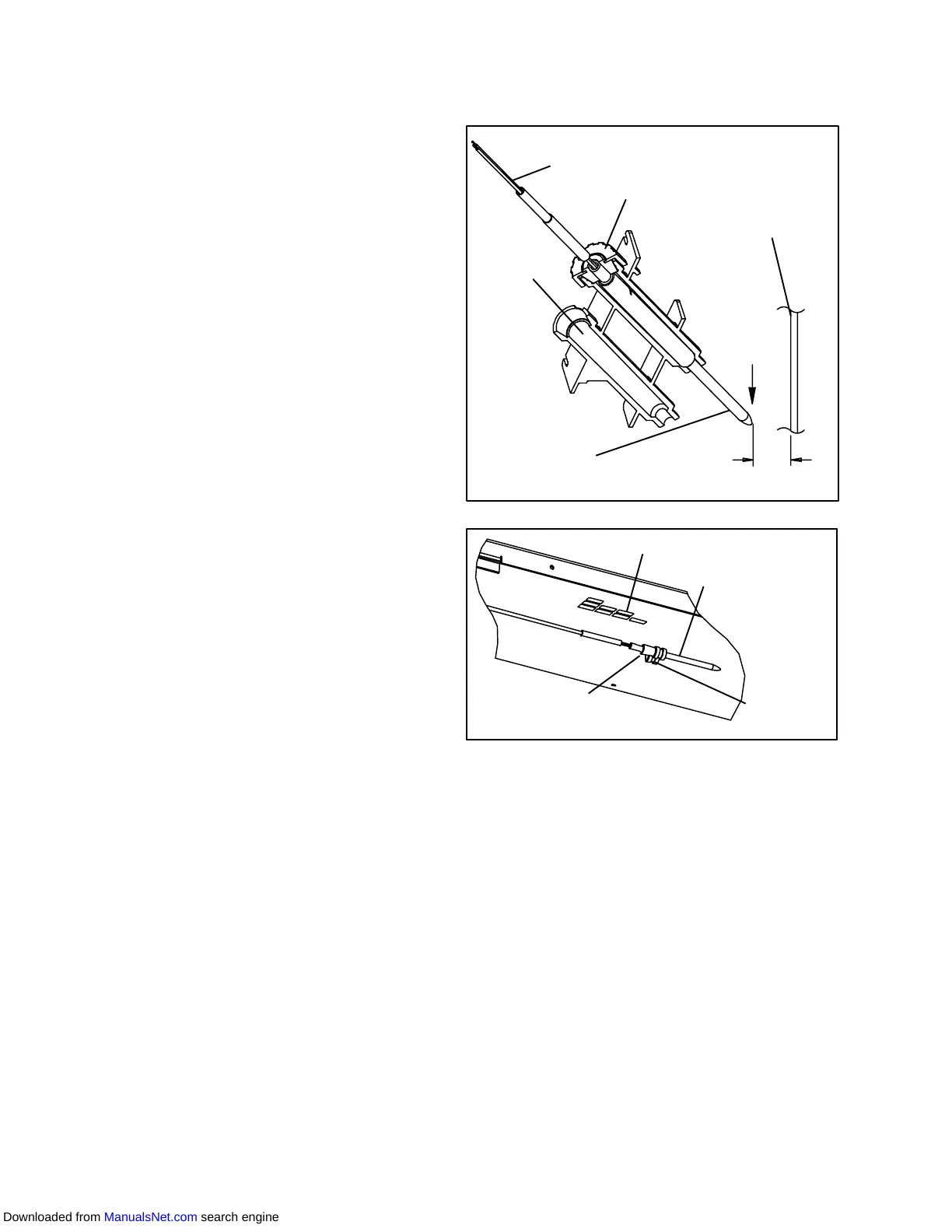
a. Sensors STS/SRS
Toproperlypositionasupplysensor,thesensor mustbe
fully inserted into the probe holder. This positioning will
give the sensor the optimum amount of exposure to the
supply air stream, and will allow the Controller to
operate correctly. Insufficient probe insertion into the
probe holder will result in poor temperature control due
to the lack of air flow over the sensor.
It isalsonecessary toensure that the probetip doesnot
contact the evaporator back panel. The design
minimum clearance of 6 mm (1/4 inch) should be
maintained (see Figure 6-29).
b. Sensor RTS/RRS
Reinstall thereturn sensor asshownin Figure 6-30. For
proper placement of the return sensor, be sure to
position the seal section of the sensor against the the
side of the mounting clamp.
c. Sensor DTS
The DTS sensor must have insulating material placed
completely over the sensor to insure the coil metal
temperature is sensed.
Cap and Grommet
Assembly
Probe
Holder
Supply Sensor
Sensor
Wires
Supply
Air
Stream
Evaporator
Back Panel
6mm
(1/4 inch)
Figure 6-29 Supply Sensor Positioning
Evaporator Grille
Combination
Sensor (Mount
in Either Clamp)
Mounting
Clamp
Seal
Figure 6-30 Return Sensor Positioning
6.22 ELECTRONIC PARTLOW TEMPERATURE
RECORDER
The microprocessor based temperature recorder is
designed to interface with the DataCORDER to log
temperature with time. The electronic recorder will
automatically record the return air, supply air , or both,
based on the setting of temperature controller
configuration code CnF37, refer to Table 3-4. The
recorder reads and records data from the Controller in
present time, under normal operating conditions.
If using the Electronic Partlow Recorder CTD P/N
12-00464-00:
Therecorder willSTOP when thepower isOFF, andthe
pen tip will remain at the last recorded temperature on
the chart. When power is applied, and the power off
period is less than three days; the pen tip will move to
25°C(77°F), thechart will advance topresent time, and
the pen tip will move to the currently recorded
temperature.
Downloaded from ManualsNet.com search engine