6-1
T -296
SECTION 6
SERVICE
NOTE
To avoid damage to the earth’ s ozone layer, use a refrigerant recovery system whenever removing refriger-
ant. When working with refrigerants you must comply with all local government environmental laws. In the
U.S.A., refer to EPA section 608.
W ARNING
Neveruseairfor leaktesting. Ithasbeen de-
termined that pressurized, mixtures of re-
frigerant and air can undergo combustion
when exposed to an ignition source.
6.1 SECTION LAYOUT
Service procedures are provided herein beginning with
refrigeration syst em service, then refrigeration syst em
component service, electrical system service,
temperature recorder service and general service.
Refer to the Table Of Contents to locate specific topics.
6.2 SERVICE VALVES
The compressor suction, compressor discharge and
liquid line service valves (see Figure 6-1) are provided
withadoubleseatandagaugeconnectionwhichenable
servicing of the compressor and refrigerant lines.
T urning the valve stem clockwise (all the way forward)
willfrontseatthevalvetocloseoffthesuction,discharge
or liquid line andopen thegauge port to thecompressor
or low side. Turning the stem counterclockwise (all the
wayout) willbackseat thevalvetoopentheconnections
and close off the port
With the valve stem midway between frontseat and
backseat,thelinesareopentoboththeconnectionsand
the gauge connection.
For example, the valve stem is first fully backseated
when connecting a manifold gauge to measure
pressure. Then, the valve is opened 1/4 to 1/2 turn to
measure the pressure.
VALVE
FRONTSEATED
(Clockwise)
VALVE
BACKSEATED
(Counterclockwise)
5
1
23
4
1. Suction, Discharge or
Liquid Line
Connection
2. Service Port
3. Stem Cap
4. Valve stem
5. Compressor Or Filter
Drier Inlet Connection
Figure 6-1 Service Valve
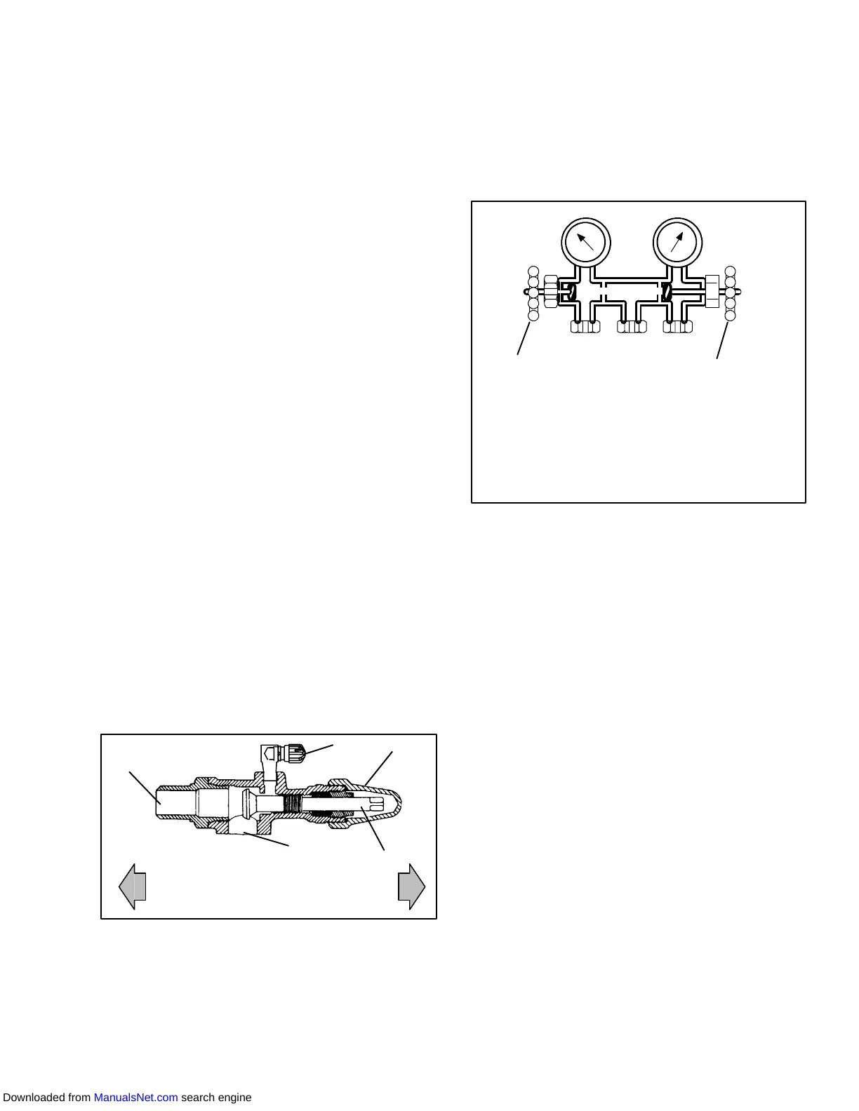
OPENED (Backseated )
HAND VALVE
CLOSED (Frontseated)
HAND VALVE
SUCTION
PRESSURE
GAUGE
DISCHARGE
PRESSURE
GAUGE
A
BC
A. CONNECTION TO LOW SIDE OF SYSTEM
B. CONNECTION TO EITHER:
REFRIGERANT CYLINDER OR
OIL CONTAINER
C. CONNECTION TO HIGH SIDE OF SYSTEM
Figure 6-2 Manifold Gauge Set
6.3. MANIFOLD GAUGE SET
The manifold gauge set (see Figure 6-2) is used to
determine system operating pressure, add refrigerant
charge, and to equalize or evacuate the system.
When the suction pressure hand valve is frontseated
(turnedallthewayin), thesuction (low)pressurecanbe
checked. When the discharge pressure hand valve is
frontseated, the discharge (high) pressure can be
checked. When both valves are open (turned
counter-clockwise all the way out), high pressure vapor
will flow into the low side. When the suction pressure
valveisopenandthedischargepressurevalveshut,the
system can be charged. Oil can also be added to the
system.
A R-134a manifold gauge/hose set with self-sealing
hoses (see Figure 6-3) is required for service of the
models covered within this manual. The manifold
gauge/hose set is available from Carrier Transicold.
(Carrier T ransicold P/N 07-00294-00, which includes
items1through6, Figure 6-3.) Toperform serviceusing
the manifold gage/hose set, do the following:
a. Preparing Manifold Gauge/Hose Set For Use
1. If the manifold gauge/hose set is new or was
exposed to the atmosphere it will need to be eva-
cuated to remove contaminants and air as follows:
2. Back seat (turn counterclockwise )both field service
couplings (see Figure 6-3) and midseat both hand
valves.
3. Connect the yellow hose to a vacuum pump and re-
frigerant 134a cylinder.
4. Evacuate to 10 inches of vacuum and then charge
with R-134a to a slightly positive pressure of 0.1 kg/
cm@ (1.0 psig).
Downloaded from ManualsNet.com search engine