6-32T -296
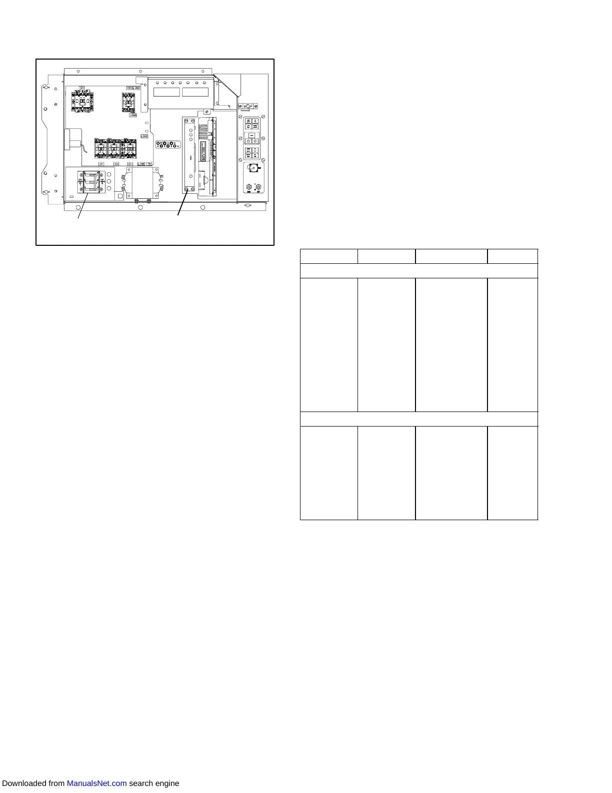
6.27 COMMUNICATIONS INTERF ACE MODULE
INSTALLATION
Communications
interface Module
CB1
Figure 6-36. Communications Interface
Installation
Units with communication interface module provision
have the required wiring installed. The provision wiring
kit (part number 76--00685--00), includes three
pre--addressed wires installed between the circuit
breaker andcommunicationinterface modulelocations.
These wires are to be connected to the module and
circuitbreakertoallowthemoduletocommunicateover
the power system. To install the module, do the
following:
W ARNING
THE UNIT POWER PLUG MUST BE DIS-
CONNECTED TO REMOVE POWER FROM
CIRCUIT BREAKER CB1
a.. CB1 is connected to the power system, see wiring
schematic. Ensure that the unit power is off AND
that the unit power plug is disconnected.
b.. Open control box, see Figure 6-36 and remove low
voltage shield. Open high voltage shield.
c.. Remove the circuit breaker panel, with circuit
breaker, from the control box.
d.. Locate, wires CB21/CIA3, CB22/CIA5 and
CB23/CIA7 that have been tied back in the wire
harness. Remove the protective heat shrink from
the ends of the wires.
e.. Attach the three wires as addressed to the LOAD
side of the circuit breaker.
f.. Refit the circuit breaker panel.
g. Fit the new RMU into the unit.
h. Remove plugs CIA, CIB and CID from the wiring
harness and attach to the module.
.i. Replace the low voltage shield.
Table 6 -6 Recommended Bolt Torque Values
BOLT DIA.
THREADS TORQUE MKG
FREE SPINNING
#4
#6
#8
#10
1/4
5/16
3/8
7/16
1/2
9/16
5/8
3/4
40
32
32
24
20
18
16
14
13
12
11
10
5.2 in-lbs
9.6 in-lbs
20 in-lbs
23 in-lbs
75 in-lbs
11 ft-lbs
20 ft-lbs
31 ft-lbs
43 ft-lbs
57 ft-lbs
92 ft-lbs
124 ft-lbs
0.05
0.11
0.23
0.26
0.86
1.52
2.76
4.28
5.94
7.88
12.72
17.14
NONFREE SPINNING (LOCKNUTS ETC.)
1/4
5/16
3/8
7/16
1/2
9/16
5/8
3/4
20
18
16
14
13
12
11
10
82.5 in-lbs
145.2 in-lbs
22.0 ft-lbs
34.1 ft-lbs
47.3 ft-lbs
62.7 ft-lbs
101.2 ft-lbs
136.4 ft-lbs
0.95
1.67
3.04
4.71
6.54
8.67
13.99
18.86
Downloaded from ManualsNet.com search engine