6-7
T -296
2
1
3
4
5
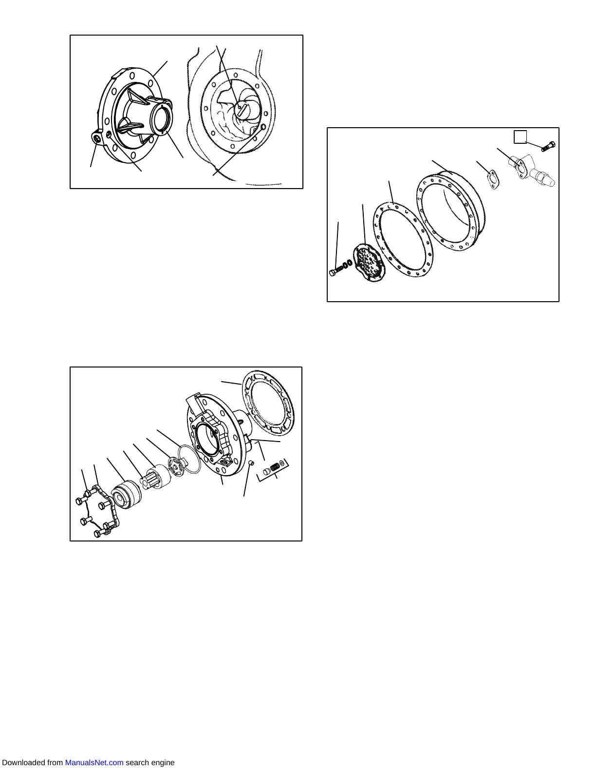
Set screw must be removed.
1. Oil Pump & Bearing
Head
2. Thrust Washer
3. Oil Pickup Tube
4. Oil Inlet Port
5. Oil Pump Inlet
Figure 6-9 Oil Pump and Bearing Head
NOTE
If the oil pump was not operating properly, the
entire oil pump & bearing head assembly must
bereplaced.Individualpartsarenotavailable.If
the pump requires inspection or cleaning, dis-
assemble and reassemble by referring to
Figure 6-10.Cleanallparts andcoat allmoving
parts with compressor oil before proceeding
with reassembly.
12
1
2
3
4
5
6
7
8
9
10
11
1. Capscrews
2. Cover
3. Reversing Assembly
4. Pinion
5. Gear
6. Drive
7. O-Ring
8. Oil Pump & Bearing
9. Set Screw
10. Relief Valve
11. Pin
12. Gasket
Figure 6-10 Low Profile Oil Pump
h. Be very careful not to damage the motor windings
when removing the motor end cover (see
Figure 6-11), as the cover fits over the winding coils.
Loosen the cap screws, break the seal and then re-
moveallcapscrewsexceptoneinthetopofthecover.
While holding the cover in place, remove the remain-
ing capscrew. Do not allow the cover to drop from its
own weight. To prevent striking the winding, remove
the cover horizontally and in line with the motor axis.
1
2
3
45
6
7
1. Strainer Screws and
Washers
2. Suction Strainer
3. Motor End Cover
Gasket
4. Motor End Cover
5. Valve Gasket
6. Suction Service Valve
7. Valve Capscrew
Figure 6-11 Motor End Cover
i. Remove the refrigerant suction strainer. If it is
removedwitheaseitmaybecleanedwithsolventand
replaced. If the strainer is broken, corroded or
clogged with dirt that is not easily removed, replace
the strainer. Install new gaskets upon reassembly.
j. Block the compressor crankshaft so that it cannot
turn. Use a screwdriver to bend back the tabs on the
lockwasher and remove the equalizer tube and lock
screw assembly. (See Figure 6-12.) The slingers at
the end of the tube draw vapor from the crankcase.
Removetherotorusingajackbolt. Insertabrassplug
intotherotorholetoprevent damage totheendofthe
crankshaft.
k. Ifthepistonringsextendbeyondthecylindertops,the
pistons can be pulled through the bottom plate open-
ing after the piston rings are compressed. A piston
ring compresser will facilitate removal. Each piston
pin is lockedin place bylock ringswhich aresnapped
into grooves in the piston wall. See Figure 6-13
l. Since the stator cannot be replaced in the field, the
terminalplate assemblyneednotbedisturbedunless
a leak exists and the plate assembly needs to be re-
placed. If noterminalplaterepair isrequired,proceed
with reassembly.
Downloaded from ManualsNet.com search engine