6-6T -296
possible internal pressure by loosening the
bolts and tapping the component with a
soft hammer to break the seal.
CAUTION
Removing the compressor motor press-fit
stator in the field is not recommended. The
rotor and stator are a matched pair and
should not be separated.
When disassembling compressor, matchmark parts so
they may be replaced in their same relative positions.
(See Figure 6-6.) Refer to Table 6-7 and Table 6-8 for
compressor wear limits and bolt torque values.
a. Place the compressor in a position where it will be
convenient to drain the oil. Remove the oil fill plug
(see Figure 6-6) to vent the crankcase. Loosen the
drainpluginbottom plateandallow theoiltodrainout
slowly. Remove the plug slowly to relieve any crank-
case pressure. Some units have a plug in the bottom
center of the crankcase which may be removed for
draining the motor end more quickly.
12 3 4 5 7
6
JACK HERE
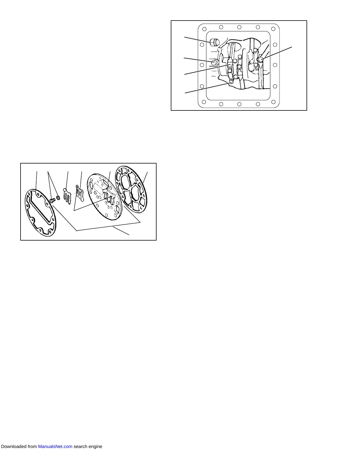
1. Cylinder Head Gasket
2. Discharge Valve
Screw & Lockwasher
3. Discharge Valve Stop
4. Discharge Valve
5. Valve Plate
6. Valve Plate Assembly
7. Valve Plate Gasket
Figure 6-7 Exploded View of Valve Plate
1
2
3
4
5
1. Oil Pressure Relief
Valve
2. Oil Return Check
Valve
3. Oil Suction Tube
4. Capscrew
5. Connecting Rod and
Cap Assembly
Figure 6-8 Bottom Plate Removed
b. Loosencylinderheadcapscrews. If the cylinderhead
is stuck, tap the center of the cylinder head with a
wooden or lead mallet. Do not strike the side of the
cylinderhead.Becarefulnot todroptheheadordam-
age the gasket sealing surface. Remove cylinder
head bolts and gasket (see Figure 6-7).
c. Removevalvestopsandvalves.Aftertheyhavebeen
removed, free the valve plate from the cylinder deck
byusingtheoutsidedischargevalvehold-downcaps-
crew as a jack screw through the tapped hole of the
valve plate. Remove the valve plate gasket.
d. Turn the compressor on its side and remove the bot-
tom plate oil suction screen and screen hold down
plate.Inspectthescreenfor holesor anaccumulation
of dirt. The screen can be cleaned witha suitablesol-
vent.
e.Matchmarkeachconnectingrodcap(seeFigure 6-8)
and connecting rod for correct reassembly. Remove
the bolts and connecting rod caps. Push the piston
rodsupas far astheywillgowithouthavingthepiston
rings extend above the cylinders.
CAUTION
The copper tube which connects to the oil
suction strainer extends out the bottom
with the bottom plate removed. Take pre-
cautions to avoid bending or breaking it
while changing crankcase positions.
f. If necessary, remove the oil return check valve. (See
Figure 6-8.) Inspect it for proper operation (flow in
one directiononly). Replacethe assemblywith anew
unit if check valve operation is impaired.
g. Toremovetheoilpump(seeFigure 6-9)removeeight
capscrews, oil pump bearing head assembly, gasket
and thrust washer.
Downloaded from ManualsNet.com search engine