6-14T -296
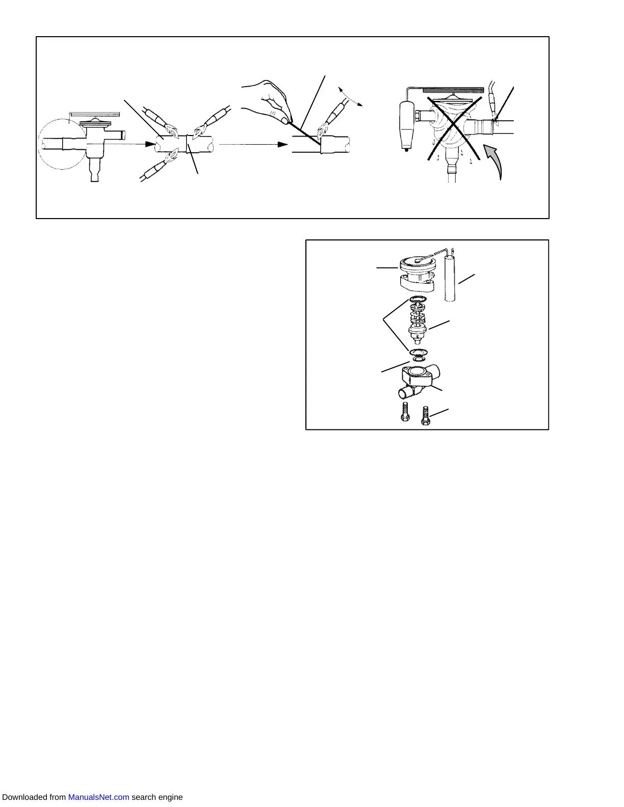
Copper Tube
(Apply heat for
10-15 seconds)
Bi-metallic T ube Connection
(Apply heat for 2-5 seconds)
Use of a wet cloth is not neces-
sary due to rapid heat dissipation
of the bi--metallic connections
Braze Rod
(’Sil-Phos” = 5.5% Silver, 6% Phosphorus)
Figure 6-21 Hermetic Thermostatic Expansion Valve Brazing Procedure
2. Removecushionclampslocatedontheinletandout-
let lines.
3. Unbraze the equalizer connection (1/4”), the outlet
connection (5/8”) and then the inlet connection
(3/8”). See Figure 6-21. Be careful to protect t he in-
sulation on the heaters and their wires.
4. Remove insulation (Presstite) from expansion valve
bulb.
5. Unstrap the bulb, located below the center of the
suction line (4 o’clock position), and remove the
valve.
b. Installing the Expansion Valve
1. Clean the suction line with sandpaper before instal-
ling bulb to ensure proper heat transfer . Apply ther-
mal grease to the indentation in the suction line.
2. Strap the thermal bulb to the suction line, making
sure bulb is placed firmly into the suction line. See
Figure 6-19 for bulb placement.
3. Insulate the thermal bulb.
4. Braze inlet connection to inlet line, see Figure 6-21.
5. Braze outlet connection to outlet line.
6. Reinstallthecushionclampson inletand outletlines.
7. Braze the equalizer connection to the equalizer line.
8. Check superheat (refer to step 6.14.1).
6.14.3 Semi--Hermetic Valve Replacement
a. Removing Expansion Valve
1 Pump down the unit per paragraph 6.4.
2 Remove insulation (Presstite) from expansion valve
bulb and power assembly and then remove thermal
bulb from the suction line (see Figure 6-19) .
3 Loosen flarenut and disconnect equalizing line from
expansion valve.
4 Remove capscrews and lift off power assembly and
removecageassembly.Checkforforeignmaterialin
valve body.
5 The thermal bulb is located below the center of the
suction line (4 o’clock position). This area must be
clean to ensure positive bulb contact.
6
2
5
3
7
1
4
1. Power Assembly
2. Body Flange Gaskets
3. Seat Gasket
4. Bulb
5. Cage Assembly
6. Body Flange
7. Body Flange Screws
Figure 6-22. Ther most atic Ex pansion Valv e -- Alco
b. Installing Expansion Valve
CAUTION
Ifthethermostaticexpansionvalveisfound
to be in need of replacement, then the
power head and cage assembly are to
replaced as a pair. They are a matched pair
and replacing one without the other will
affect the superheat setting.
1 Replace all gaskets, making sure to lightly coat with
oil. Insert cage and power assembly and bolts.
T ighten bolts equally. Fasten equalizer flare nut to
expansion valve.
2 Leak check the unit per paragraph 6.5. Evacuate
and dehydrate unit per section 6.6. Add refrigerant
charge per section 6.7.
3 Clean suction line with sandpaper before installing
bulb to ensure proper heat transfer . Strap thermal
bulbtosuction line,makingsure bulb is placedfirmly
Downloaded from ManualsNet.com search engine