6-15
T -296
into the indentation of the suction line. See
Figure 6-19 for bulb placement.
4 Check superheat. (Refer to paragraph 6.14.2 step
6.14.1 ) Container box temperature should be at
-- 18°C(0°F).
6.15 EVAPORATOR COIL AND HEATER
ASSEMBLY
The evaporator section, including the coil, should be
cleaned regularly. The preferred cleaning fluid is fresh
water or steam. Another recommended cleaner is
Oakite 202 or similar , following manufacturer’s
instructions.
The two drain pan hoses are routed behind the
condenser fan motor and compressor. The drain pan
line(s) must be open to ensure adequate drainage.
6.15.1 Evaporator Coil Replacement
a. Pump unit down. (Refer to paragraph 6.4.)
b. With power OFF and power plug removed, remove
the screws securing the panel covering the evapora-
tor section (upper panel).
c. Disconnect the defrost heater wiring.
d. Disconnect the defrost temperature sensor (see Fig-
ure Figure 2-2 from the coil. .
e. Remove middle coil support.
f. Remove the mounting hardware from the coil.
g. Unsolder thetwocoilconnections, oneat thedistribu-
tor and the other at the coil header.
h. After defective coil is removed from unit, remove
defrost heaters and install on replacement coil.
i. Install coil assembly by reversing above steps.
j. Leakcheckconnectionsperparagraph6.5.Evacuate
the unit per paragraph6.6 andadd refrigerant charge
per paragraph 6.7.
6.15.2 Evaporator Heater Replacement
a.Beforeservicing unit, make suretheunit circuit break-
ers (CB-1 & CB-2) and the start-stop switch (ST) are
intheOFFposition,andthatthepowerplugandcable
are disconnected.
b. Remove the lower access panel (Figure 2-1) by
removing the T.I.R. locking device lockwire and
mounting screws.
c. Determine which heater(s) need replacing by check-
ingresistance on eachheater.Refertoparagraph2.3
for heater resistance values
d. Remove hold-down clamp securing heaters to coil.
e. Lift the bent end of the heater (with the opposite end
down and away from coil). Move heater to the side
enough to clear the heater end support and remove.
6.16 EVAPORATOR FAN AND MOTOR ASSEMBLY
The evaporator fans circulate air throughout the
container by pulling air in the top of the unit. The air is
forced through the evaporator coil where it is either
heated or cooled and then discharged out the bottom of
the refrigeration unit into the container. The fan motor
bearings are factory lubricated and do not require
additional grease.
6.16.1 Replacing The Evaporator Fan Assembly
W ARNING
Always turn OFF the unit circuit breakers
(CB-1 & CB-2) and disconnect main power
supply before working on moving parts.
a. Remove upper access panel (see Figure 2-2) by
removing mounting bolts and T.I.R. locking device.
Reachinsideof unit and removethe Ty-Rapsecuring
the wire harness loop. Then unplug the connector by
twisting to unlock and pulling to separate.
b. Loosenfour1/4-20clampboltsthatarelocatedonthe
undersideof thefandeck at the sidesof theof thefan
assembly. Slide the loosened clamps back from the
fan assembly.
c. Slide the fan assembly out from the unit and place on
asturdyworksurface.
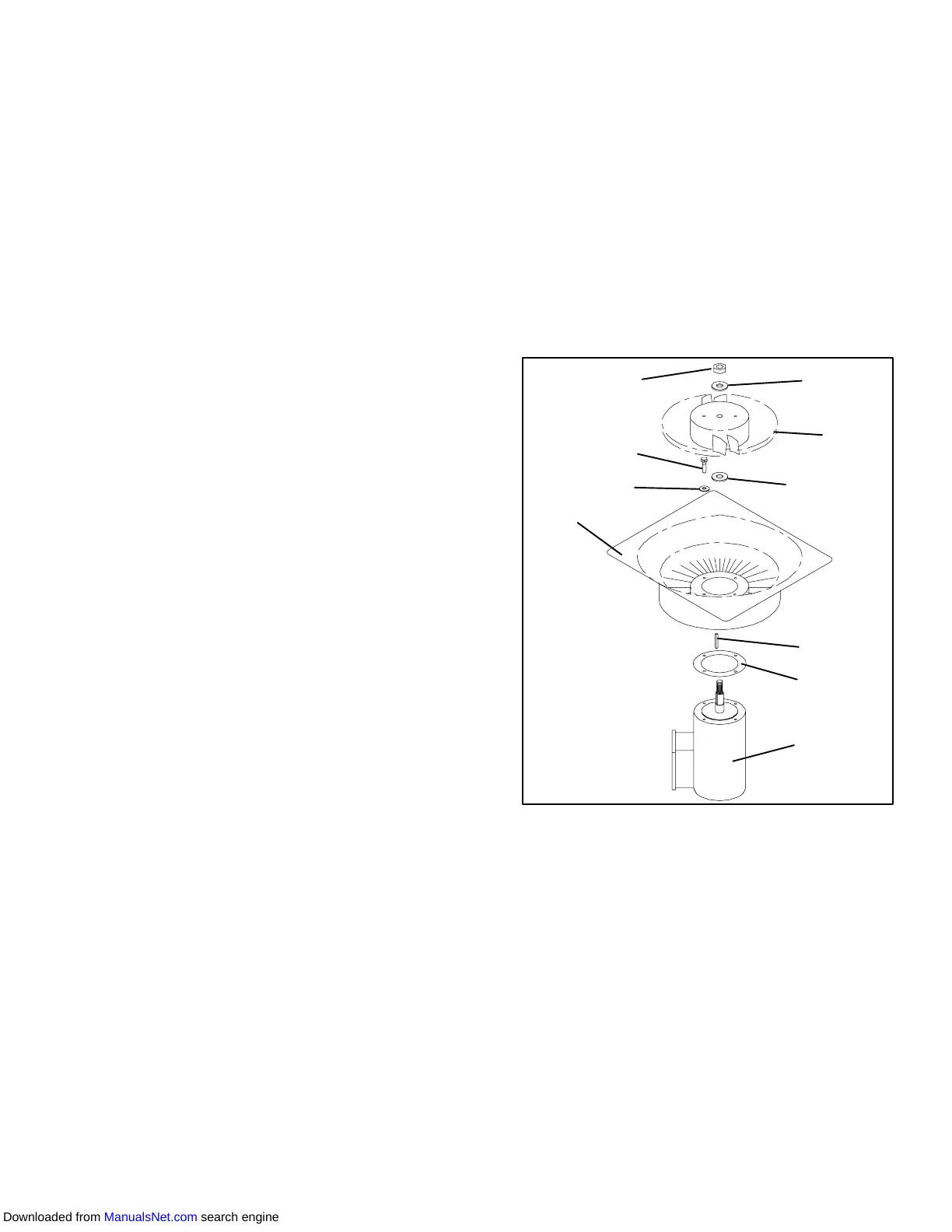
1
2
3
4
5
6
5
7
8
9
1. Stator
2. Flat washer, 1/4
3. Bolt, 1/4-20 x 3/4
4. Locknut, 5/8-18
5. Flat washer, 5/8
6. Impeller Fan
7. Key
8. Mylar Protector
9. Evaporator Motor
Figure 6-23. Evaporator Fan Assembly
6.16.2 Disassemble The Evaporator Fan Assembly
a. Attach a spanner wrench to the two 1/4-20 holes
locatedin the fanhub. Loosenthe 5/8-18shaft nut by
holding the spanner wrench stationary and turning
the 5/8-18 nut counter-clockwise (see Figure 6-23).
b. Remove the spanner wrench. Use a universal wheel
pullerandremovethefanfrom theshaft. Removethe
washers and key.
c. Remove the four 1/4-20 x 3/4 long bolts that are
located under the fan that support the motor and sta-
tor housing. Remove the motor and plastic spacer.
6.16.3 Assemble The Evaporator Fan Assembly
Downloaded from ManualsNet.com search engine