124 Chadwick-Helmuth Company, Inc.
Chapter 6 - Maintenance
CAUTION: This backward-battery problem is much easier to cause
in European countries where the D-batteries have no tips on the
positive end. Both ends are flat, so the user must read the label on
the battery.
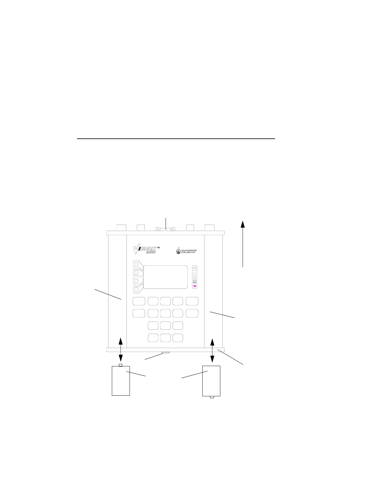
6.3.1.3 Battery Insertion Diagram
For a diagram of how to insert batteries into the Vibrex unit, see the
illustration below.
6.3.1.4 Removal
Remove batteries from the Vibrex unit, as follows:
1. Using a Phillips screwdriver, turn the large Phillips screw on the
unit’s battery end plate (15), one quarter turn counter-clockwise.
2. Carefully remove the battery end plate.
SPACE
+ / -
PRINT
7
STU
4
JKL
OFF
# % @
0
ON
PQR
8
VWX
9
YZ
5
MNO
6
REVIEW
GO BACK
1
ABC DEF
2
GHI
3
START
:
CONNECTOR SUBPANEL
SUBPANEL
POINTING
UPWARD
LEFT-
SIDE
HAND
GRIP
RIGHT-
SIDE
HAND
GRIP
BATTERIES
(4 SIZE D)
+
+
BATTERY END
PLATE
PHILLIPS SCREW