142 Chadwick-Helmuth Company, Inc.
Chapter 6 - Maintenance
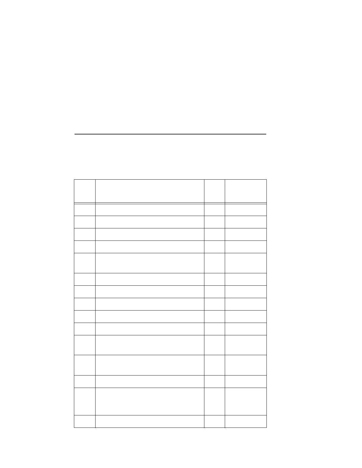
6.3.7.1 Parts List
The following table lists the Vibrex 2000 and Vibrex 2000 Plus parts
called out in the procedures given in this chapter (and related parts),
including their names, part, and reference numbers:
Ref.
No.
Part Name Qty.
Part
Order No.
01 Chassis (housing/keypad assembly) 1 820-13588
02 Shield 1 567-13586
03 Screw, 4-40 by 3/8, Phillips, trilobular 4 651-4533C
04 Connector end plate, silk screened 1 578-13574
05 MS (military standard) panel jack
No. 8-4S
2 403-0841
06 Nut, 4-40, nylon lock standard 8 652-45NS
07 Screw, 4-40 by 3/8, Phillips 16 651-4523
08 Standoff, 4-40, 1/2 in. nylon hex 8 660-3444
09 MS panel connector No. 10-6S 2 403-1063
10 Standoff, male/female, No. 4, by 1.75 8 660-14E4
11 Battery contact PCB assembly;
includes fuse (F1) and spring
2 14325-2
40 Battery contact PCB assembly;
includes fuse (F1) and spring
2 14325-1
12 Screw, 4-40 by 1/4, Phillips, black 8 651-4521
14 Main PCB (PCB/graphics module
assembly); For 13590-2:
For 13590-3 and 14990:
1 820-13759
820-14987
15 Battery end plate 1 568-14318