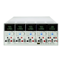
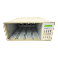
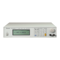
Programmable DC Electronic Load 63600 Series Operation & Programming Manual
Figure 4-12 63600-1 System I/O Port Connector
Table 4-10 63600-1 Pin Assignments of the System I/O Port Connector
1. TTL High Level Voltage is 5V.
2. TRIG_ SEQ: External trigger input signal used to increment to next
sequence setting. TTL Level, falling edge, pulse width ≥1μs.
3. DGNDC: Digital signal reference ground.
4. EXT_WAVE [1:2]: External input signals for first or second channels.
Input range is from 0 to 10V.
5. VMON [1:2]: Voltage monitor signals for the first or second channel.
Output range is from 0 to 10V.
6. IMON [1:2]: Current monitor signals for the first or second channel.
Output range is from 0 to 10V.
7. AGNDC: Analog signal reference ground.
4.14 Using the Synchronous Cable
63600 Series supports up to 4 sets of mainframe synchronous load control, see 4.7.1 for the
configuration setting. The connection between mainframe is via the System Bus connector
on the rear panel. Figure 4-13 & Figure 4-14 show the internal wiring of synchronous cable
and MASTER/ SLAVE connection of mainframe. It requires another synchronous cable if one
more SLAVE is desired. Be sure to connect the MASTER port to the EXTENDED port of
previous cable and plug in the SLAVE port to mainframe, and so forth.
The synchronous cable connection of two mainframes is to turn on the terminal resistor of
each mainframe and press and together to enter into the CONFIGURE page.
Select 3.REMOTE and press to go to REMOTE page and select 2.SYSTEM BUS to
set the ADDRESS to be 01~04 (the address of the two mainframes cannot be the same to
avoid confliction) and TERMINATOR to be ON.
 Loading...


