EasyManuals Logo

Chroma 63600-2 User Manual

Default Icon
258 pages
To Next Page IconTo Next Page
To Previous Page IconTo Previous Page
Page #55 background imageLoading...
Page #55 background image
Operation Overview
3-3
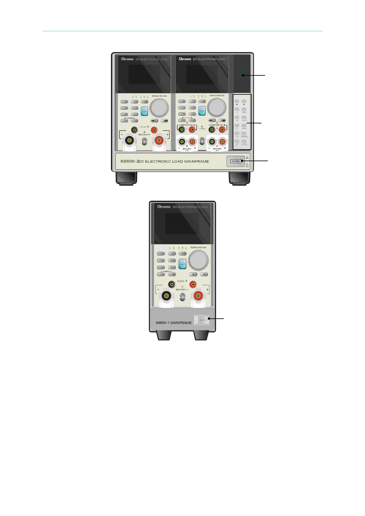
Figure 3-3 Front Panel of 63600-2
Figure 3-4 Front Panel of 63600-1
3.3 Rear Panel Description
The Mainframe rear panel includes two System Bus ports, a USB port, an optional GPIB
connector, an optional Ethernet connector, a System I/O port, an AC LINE socket, a fuse
holder, and five air holes of the fan cooling.
The rear panels of Mainframe 63600-5, 63601-5, 63600-2, 63600-1are shown in Figure 3-5,
Figure 3-6, Figure 3-7 and Figure 3-8.
Power key
Power key
LED
Display
Keypads

Table of Contents

Questions and Answers:

Question and Answer IconNeed help?

Do you have a question about the Chroma 63600-2 and is the answer not in the manual?

Chroma 63600-2 Specifications

General IconGeneral
BrandChroma
Model63600-2
CategoryPower Supply
LanguageEnglish

Related product manuals