Verification
7.3.2.3 Checking Low ohm Range
A. Press till VFD shows CR and press to light up the L range LED
indicator.
B. The current shunt range is 250A. Press to input the resistance listed in Table
7-10 . Press to enable load, and see value of DMM(V) to adjust the value of DC
source same as the setting value for testing model before, and waited for 30 seconds,
record the voltage that passes through the load input terminals DMM (V) and the shunt
current reading DMM (I). Calculate the values of the resistance via DMM (V)/DMM (I).
Check the values to fit the specification.
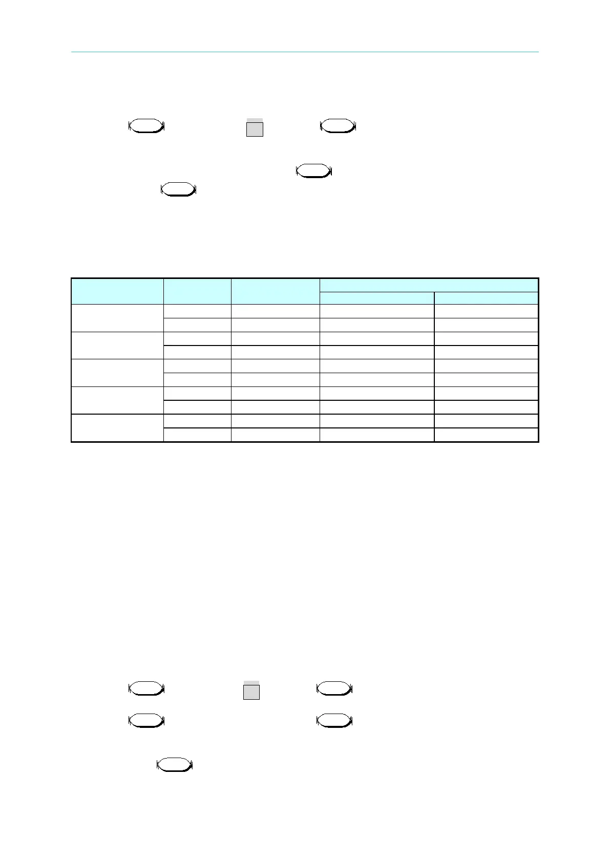
Table 7-10
Appropriate Conductance (S)
63630-600-15
63640-150-60
63630-80-60
63610-80-20
63640-80-80
7.3.3 CV Mode Verification
This test verifies if the voltage programming and reading value on the front panel display are
within specifications when the module is operating in CV mode. For each DMM (V) reading,
the front panel display of voltage should be equivalent to:
Load module reading in volts = DMM (V) reading in volts ± inaccuracy.
7.3.3.1 Checking High Voltage Range
A. Connect the Load module, DC source, DMM and current shunt as Figure 7-1 shows.
Use DMM (V) to measure the voltage passing through the module’s input terminal. Be
careful in making connections so that contact resistance voltage drop will not affect the
readings.
B. Press till VFD shows CV and press to light up the H range LED
indicator.
C. Press to set load voltage and press to set limit current. The DC Source
voltage output and limit current settings are based on the voltage/current values listed in
Table 7-11.
D. Next, press to enable the load and wait for 30 seconds to record the voltage
passing through the negative input terminal.