Local Operation
B. Dual Channel Module
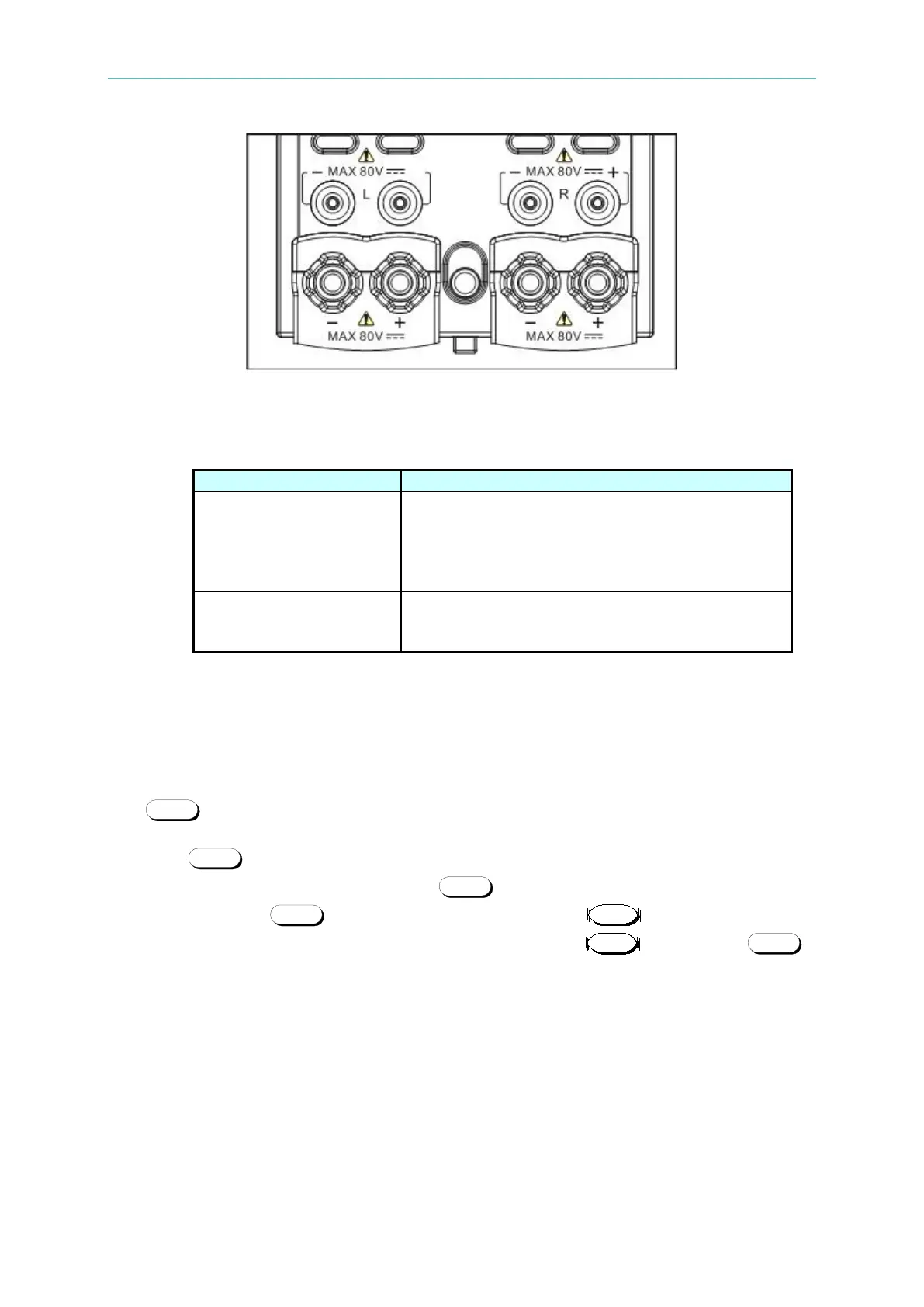
Figure 4-7 Front Panel Connectors of the Module
Table 4-4 Definition for Front Panel Connectors on the Module
A connector for remote sensing directly at the UUT
terminal eliminates any voltage drop on the
connecting cable. If it is not connected, the sensing
terminal switches automatically to the LOAD
Input connectors of the Electronic Load for
connecting to the UUT. The red one is for positive
(+) and the black one is for the negative (-) pole.
4.3 Selecting the Channel for a Dual Channel
Module
The key is used to select one of the channels for a dual channel module, like the
model Chroma 63610-80-20. To edit the channel settings, you must select a channel first.
Press the key to select left channel or right channel for the dual channel module,
then the LED “L” or LED “R” above the key lights up. If the load model is a single
channel module, the key does not exist, it is instead of key. The model
Chroma 63630-80-60 is a single channel module, so it has the key, without
key.
4.4 Setting Operation Mode of Static Load
There are five operation modes for static load: constant current (CC), constant resistance
(CR), constant voltage (CV), constant power (CP), and constant impedance (CZ).