Note: The 12 registers of each output must be written and read at once (as a group), otherwise
it will respond with an error.
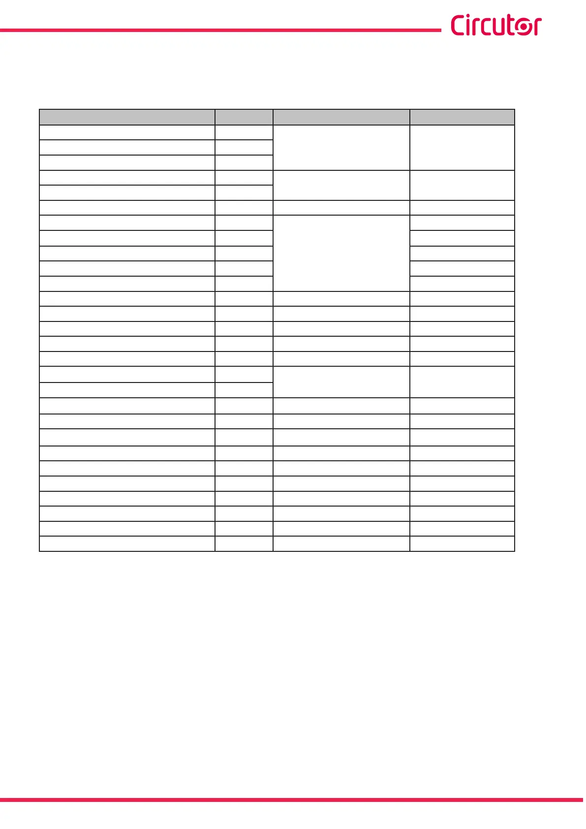
Table 61: Units and maximum and minimum values of the programming variables of the digital outputs�
Variable Units Maximum Minimum
Phase-neutral voltage
(53)
V
10000 * voltage ratio
(50)
0Phase-phase voltage
(53)
V
Neutral voltage
(53)
V
Current mA
10000 *current ratio
(51)
0
Neutral current mA
Frequency
(54)
Hz 70000 40000
Active power
(52)
W
180 000 000
-180 000 000
Apparent power
(52)
VA
0
Total reactive power
(52)
var -180 000 000
Inductive reactive power
(52)
var 0
Capacitive reactive power
(52)
var 0
Power factor
(53)
- 100 -100
Cos φ
(53)
º 100 -100
Voltage THD %
(55)
% 1000 0
Current THD %
(55)
% 1000 0
Maximum Demand of Current mA 10000 *current ratio
(51)
0
Maximum Demand of Active Power
W
180 000 000 0
Maximum Demand of Apparent Power VA
Instantaneous Flicker (Pinst)
(53)
WA 99999 0
K-factor
(53)
- 9999 0
Voltage peak factor
(53)
- 2000 0
Current peak factor
(53)
- 2000 0
% V Unbalance (Kd)
(54)
- 100000 0
% I Unbalance (Kd)
(54)
- 100000 0
% V Asymmetry(Ka)
(54)
- 100000 0
% I Asymmetry(ka)
(54)
- 100000 0
Quality event - 1 0
Transient - 1 0
(50)
The voltage ratio is the ratio between the primary and secondary voltage.
(51)
The current ratio is the ratio between the primary and secondary current.
(52)
The three-phase powers accept up to 540 000 000 W.
(53)
Variables with 2 decimals.
(54)
Variables with 3 decimals.
(55)
Variables with 1 decimals.
247
Instruction Manual
CVM-A1000 - CVM-A1500