6�3�10�14�- Transistor digital outputs
The Maximum Value and Minimum Value conguration variables occupy 2 registers each.
All other variables occupy 1 register each.
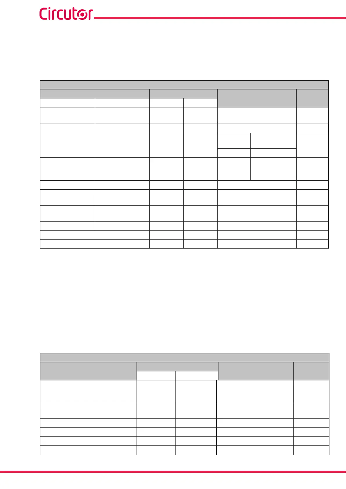
Table 62: Modbus memory map: Conguration variables (Transistor digital outputs).
Conguration of Transistor Digital Outputs
Configuration variable
Address
Valid data margin
Default
value
Alarm Impulse output
Output 1 Output 2
Maximum value
(56)
Energy meter
factor
4E20-4E21 4E34-4E35 Table 61 0
Min. value
(56) -
4E22-4E23 4E36-4E37
Table 61 0
Delay in the
connection (ON)
High period 4E24 4E38
Alarm Impulse
output
0
0 a 999 s. 1 a 65536
(57)
Delay in the
disconnection
(OFF)
Low period 4E25 4E39 0 a 999 s. 1 a 65536
(57)
0
Pre-alarm value
-
4E26 4E3A 0 al 100 % 0
Output status - 4E27 4E3B
0 : Normally open
1: Normally closed
0
Interlocking (latch) - 4E28 4E3C
0 : Unlocked
1: Locked
0
Not used Not used 4E29 4E3D
0
0
Variable code 4E2A 4E3E Table 32 0
Module no. 4E2B 4E3F
0
0
(56)
When programming the maximum and minimum values, the decimals for the variable selected must be includ-
ed.
(57)
The programmed value is a multiple of 10 ms, i.e. when programming 1 the impulse will be at its minimum value
of 10 ms.
Note: The 12 registers of each output must be written and read at once (as a group), otherwise
it will respond with an error.
6�3�10�15�- Digital inputs
The Input Name conguration variable occupies 4 registers.
The Units conguration variable occupies 3 registers.
All other variables occupy 1 register each.
Table 63:Modbus memory map: Conguration variables (Digital Inputs).
Conguration of Digital Inputs
Configuration variable
Address
Valid data window
Default
value
Input 1 Input 2
Mode 4FB0 4FBC
-1: Tariff
0: Logic state
> 0:Impulses
(58)
0
Logic (Logic state) 4FB1 4FBD
0: positive
1: Negative
0
No. of decimals (Impulses) 4FB2 4FBE 0 to 5
0
Not used 4FB3 4FBF 0 0
Input name (impulses)
(59)
4FB4 - 4FB7 4FC0 - 4FC3 8 characters “INPUT”
Units (Impulses)
(59)
4FB8 - 4FBA 4FC4 - 4FC6 6 characters -
(58)
When programming a value of more than 1, programme the impulse operating mode and energy meter factor
248
CVM-A1000 - CVM-A1500
Instruction Manual