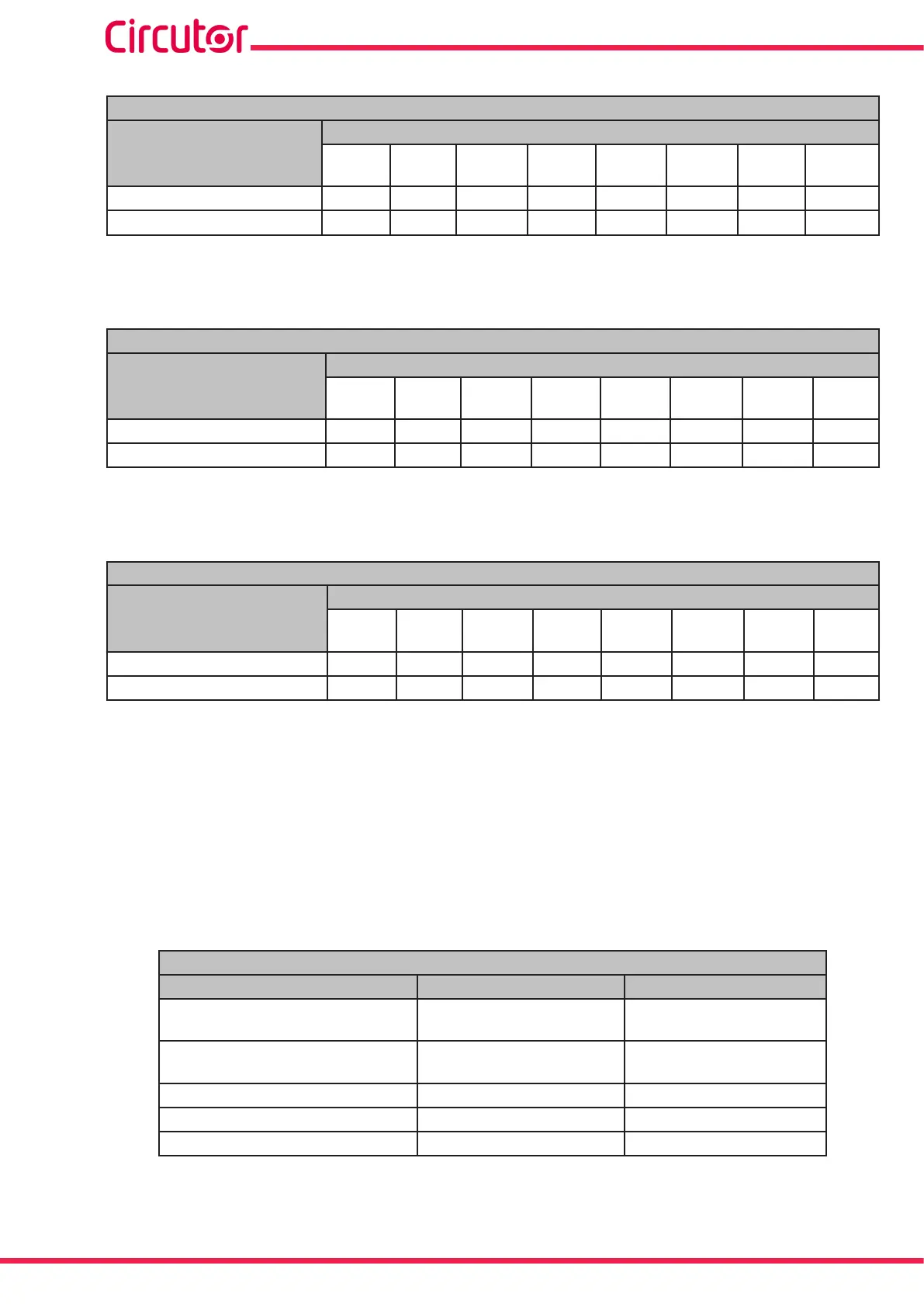
Table 112: Modbus memory map: Manual programming of outputs, expansion modules (Table 3)�
Manual programming of transistor digital outputs: Slot 2
Configuration variable
Address
Output
1
Output
2
Output
3
Output
4
Output
5
Output
6
Output
7
Output
8
Programming status C810
C824 C838 C84C C874 C874 C888 C89C
Value
C811
C825 C839 C84D C875 C875 C889 C89D
Note: The 2 registers must be written at once (as a group), otherwise it will respond with an
error.
Table 113: Modbus memory map: Manual programming of outputs, expansion modules (Table 4)�
Manual programming of transistor digital outputs: Slot 3
Configuration variable
Address
Output
1
Output
2
Output
3
Output
4
Output
5
Output
6
Output
7
Output
8
Programming status CBF8
CC0C CC20 CC34 CC48 CC5C CC70 CC84
Value
CBF9
CC0d CC21 CC35 CC49 CC5D CC71 CC85
Note: The 2 registers must be written at once (as a group), otherwise it will respond with an
error.
Table 114: Modbus memory map: Manual programming of outputs, expansion modules (Table 5)�
Manual programming of transistor digital outputs: Slot 4
Configuration variable
Address
Output
1
Output
2
Output
3
Output
4
Output
5
Output
6
Output
7
Output
8
Programming status CFE0
CFF4 D008 D01C D030 D044 D058 D06C
Value
CFE1
CFF5 D009 D01D D031 D045 D059 D06D
Note: The 2 registers must be written at once (as a group), otherwise it will respond with an
error.
7�3�4�3�- Programming the digital inputs
The following functions are implemented for these variables:
Function 0x04: reading registers.
Function 0x10: Writing multiple registers.
Table 115:Modbus memory map: Digital inputs, expansion modules (Table 1)�
Conguration of Digital Inputs
Configuration variable
Valid data window
Default value
Mode
0: Logic state
> 0:Impulses
(83)
0
Logic (Logic state)
0: positive
1: Negative
0
Input name (impulses)
(84)
8 characters “INPUT”
Units (Impulses)
(84)
6 characters -
No. of decimals (Impulses) 0 to 5
0
(83)
When programming a value of more than 1, program the impulse operating mode and energy meter factor for
this mode simultaneously.
(84)
the characters must be sent in hexadecimal.
286
CVM-A1000 - CVM-A1500
Instruction Manual