10-38
Cisco ASR 1000 Series Aggregation Services Routers Hardware Installation Guide
OL-13208-11
Chapter 10 Cisco ASR 1002-X Router Overview and Installation
Cisco ASR 1002-X Router Power Supplies
To connect the +24 VDC power supply in the Cisco ASR 1002-X Router, follow these steps:
Step 1 At the rear of the router, ensure that the power Standby switch is in the Standby position.
Step 2 Ensure that the positive and negative leads are disconnected from the site power source and the source
circuit breaker is turned off.
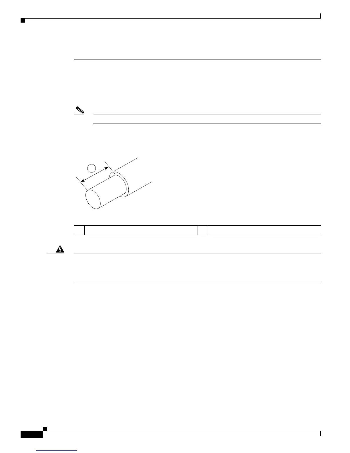
Step 3 Using a wire stripper, strip the recommended amount of wire insulation, which is 1.5 cm (0.6 inch) from
the negative, positive, and ground leads.
Note The stripping length is common to all types of wire used.
Figure 10-26 shows the wire strip and lead.
Figure 10-26 Stripping Wire for the +24 VDC Terminal Block
Warning
Remove the covering from exactly the specified length of each wire. If you strip too much of the
covering, exposed wire protruding from the terminal block will create an electrical hazard. If you
strip too little of the covering, the wire might not make a good contact with the terminal, or it might
not be held securely in place in the terminal.
1 Lead wire stripping area — —

 Loading...


