14-57
Cisco ASR 1000 Series Aggregation Services Routers Hardware Installation Guide
OL-13208-11
Chapter 14 Removing and Replacing FRUs from the Cisco ASR 1000 Series Routers
Removing and Replacing the Cisco ASR 1006 Router Power Supplies
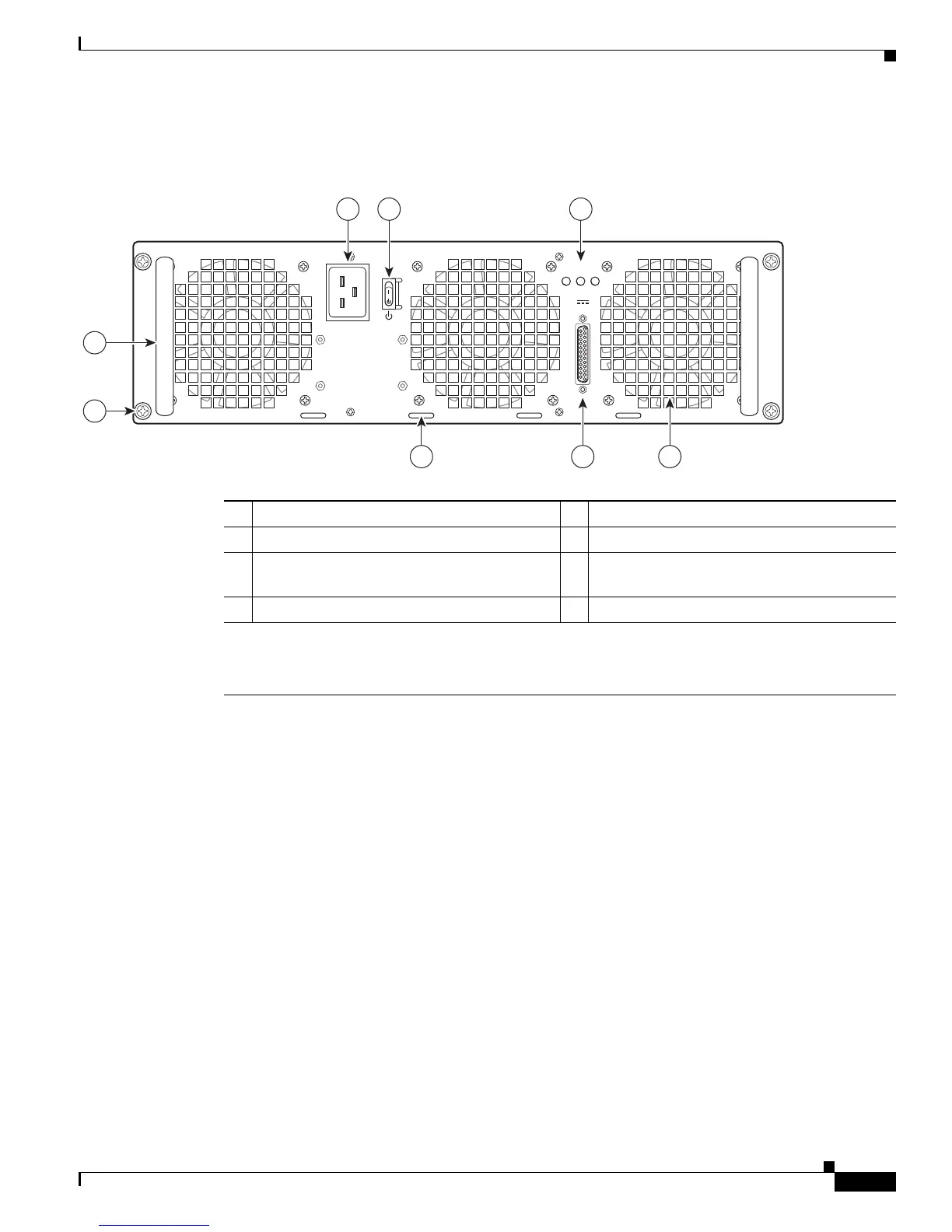
Figure 14-38 shows the ASR1006-PWR-AC power supply of the Cisco ASR 1006 Router.
Figure 14-38 Cisco ASR 1006 Router AC Power Supply (ASR1006-PWR-AC)
1 AC power supply fan 5 AC power supply handle
2 DB-25 alarm connector* 6 AC power inlet
3 Cable tie-wrap tabs 7 AC power supply Standby switch. A Standby
switch is not considered a disconnect.
4 AC power supply captive screws 8 AC power supply LEDs
*For information about the DB-25 alarm connector, how it works, and Cisco ASR 1000 series route processor LEDs, see “How
Cisco ASR1000-RP Alarm Monitoring Works” section on page 2-20.
Note: Shielded cables must be used to connect to the DB-25 alarm connector on both the AC and DC power supplies, in order
to comply with FCC/EN55022/CISPR22 Class A emissions requirements.
280029
OUTPUT INPUT INPUT
FAIL OK OK
ALARMS
60V
1A MAX
100-240V~ 16-7A
50-60HZ
This unit might have more than
one power supply connection.
All connections must be removed
to de-energize the unit.
2 13
4
5
6 7
8

 Loading...


