14-58
Cisco ASR 1000 Series Aggregation Services Routers Hardware Installation Guide
OL-13208-11
Chapter 14 Removing and Replacing FRUs from the Cisco ASR 1000 Series Routers
Removing and Replacing the Cisco ASR 1006 Router Power Supplies
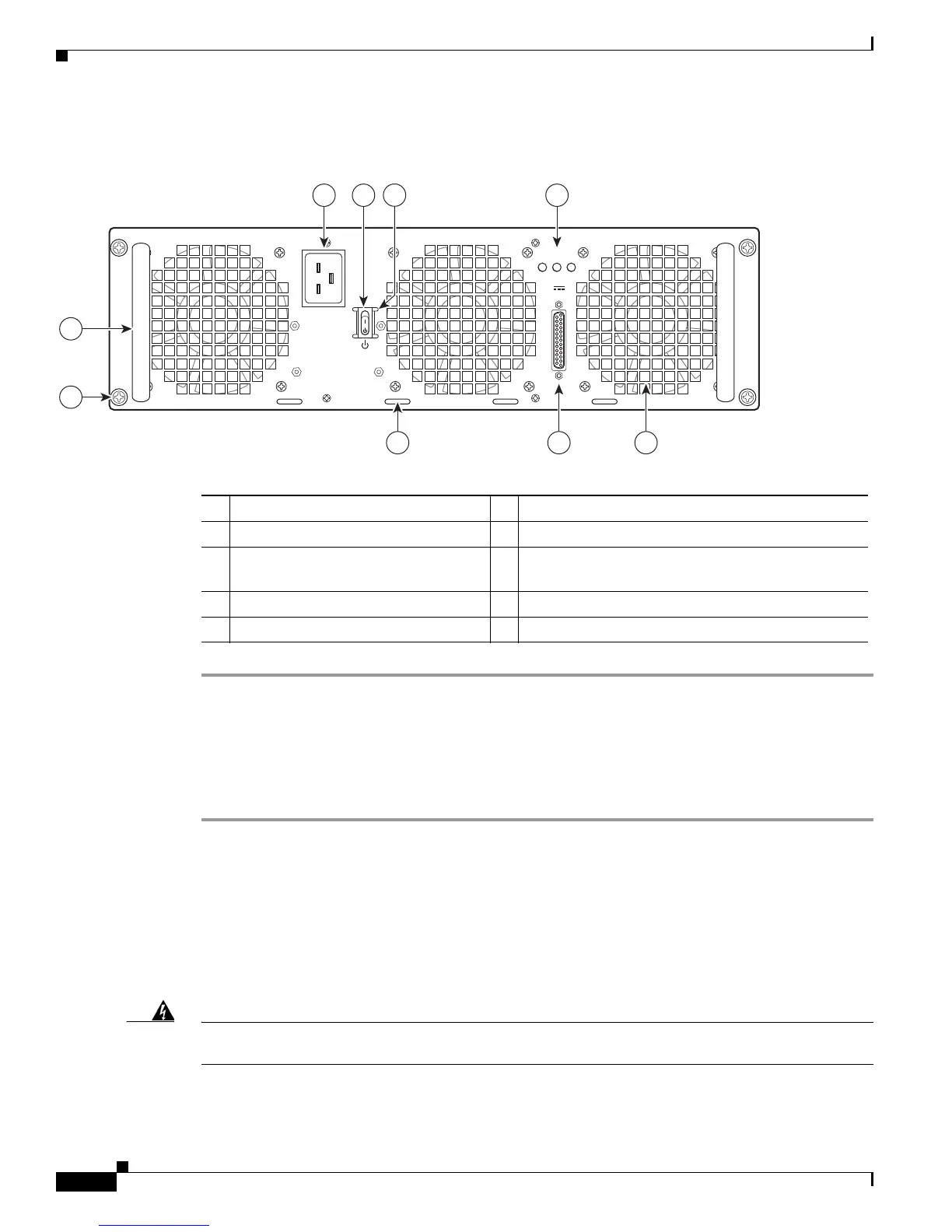
Figure 14-39 shows the ASR1013/06-PWR-AC power supply of the Cisco ASR 1006 Router.
Figure 14-39 Cisco ASR 1006 Router AC Power Supply (ASR1013/06-PWR-AC)
Step 1 Insert an AC power supply in power supply slot 0 or power supply slot 1 until it is fully seated.
Step 2 Tighten the captive screws.
Step 3 Insert the AC power cable.
Step 4 Plug the power supply cable into the power source.
Step 5 Turn the power supply Standby switch to the On (|) position.
This completes the procedure for installing the AC power supply in the Cisco ASR 1006 Router.
Removing and Replacing a DC Power Supply in Cisco ASR 1006 Router
This section provides information about removing and installing a DC power supply in the Cisco
ASR 1006 Router.
Warning
When you install the unit, the ground connection must always be made first and disconnected last.
Statement 1046
1 AC power supply fan 6 AC power inlet
2 DB-25 alarm connector 7 AC power supply Standby switch
3 Tie-wrap tab 8 Protective shielding on both sides of the Standby
switch
4 AC power supply captive screw 9 AC power supply LEDs
5 AC power supply handle — —
253916
OUTPUT INPUT INPUT
FAIL OK OK
ALARMS
60V
1A MAX
100-240V~ 16-7A
50-60HZ
This unit might have more than
one power supply connection.
All connections must be removed
to de-energize the unit.
2 13
4
5
6 7
9
8

 Loading...


