SUMMARY STEPS
1.
At the rear of the router, check that the power Standby switch is in the Standby position.
2.
Ensure that the positive and negative leads are disconnected from the site power source and the source
circuit breaker is turned off.
3.
Using a wire stripper, strip the recommended amount of wire insulation which is 15mm (0.6 inch) from
the negative, positive, and ground leads.
4.
Using a 3.5mm screwdriver, insert the screwdriver at an angle to release the spring while you install the
stripped lead wire as shown in the image.
5.
Carefully push the screwdriver at an angle forward until you relieve the spring contact.
6.
With the screwdriver still inserted, gently push the lead wire (ground lead first) in until the copper wire,
as shown in the image, is no longer visible (see in the following image).
7.
After the lead wire is fully inserted, hold the lead wire in place by pressing inward while you remove the
screwdriver to release the spring to tension down on the installed lead wire, then perform these steps:
8.
Repeat Steps 5 through Step 10 for each lead wire.
9.
After inserting the ground wire, leave an extra service loop in the ground lead to ensure that the ground
lead is the last lead to disconnect from the power supply if a great deal of strain is placed on all three leads
as shown in the following image.
10.
After tightening the receptacle screw for the ground, and leaving the extra service loop in the ground lead,
use a cable tie to secure the three leads to the power supply faceplate tie-wrap tab as shown in the above
imave, item 5.
11.
Turn on the branch source breaker.
12.
Place the power supply standby switch to the On (|) position. The power supply LEDs light when power
is supplied to the router.
DETAILED STEPS
Step 1
At the rear of the router, check that the power Standby switch is in the Standby position.
Step 2
Ensure that the positive and negative leads are disconnected from the site power source and the source circuit breaker
is turned off.
Step 3
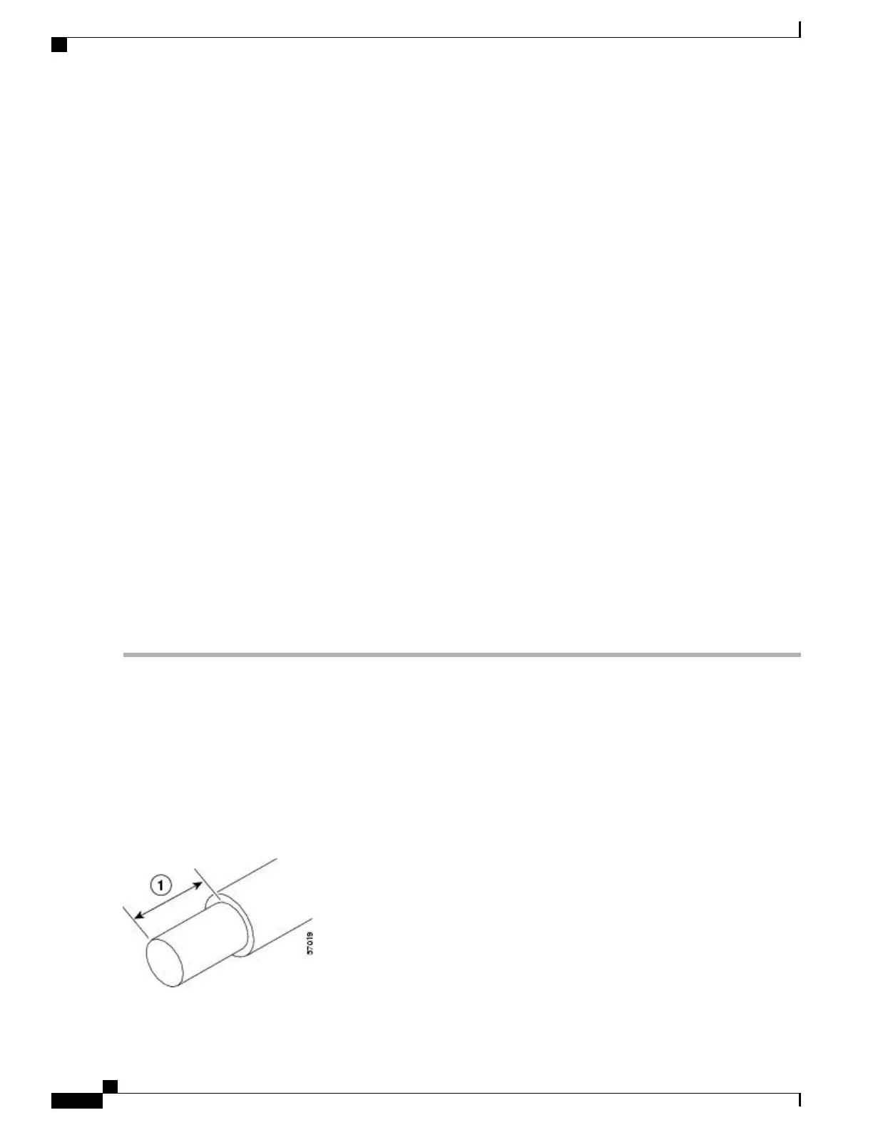
Using a wire stripper, strip the recommended amount of wire insulation which is 15mm (0.6 inch) from the negative,
positive, and ground leads.
The stripping length is common to all types of wire used.Note
The following image shows the wire strip and lead.
Figure 107: Stripping Wire for the +24 VDC Terminal Block
Cisco ASR 1000 Series Router Hardware Installation Guide
266
Cisco ASR 1002 Router Overview and Installation
Connecting Cisco 24 VDC Power Supply

 Loading...


