——
Lead wire stripping area1
Remove the covering from exactly the specified length of each wire. If you strip too much of the covering,
exposed wire protruding from the terminal block will create an electrical hazard. If you strip too little of the
covering, the wire might not make a good contact with the terminal, or it might not be held securely in place
in the terminal.
Warning
Step 4
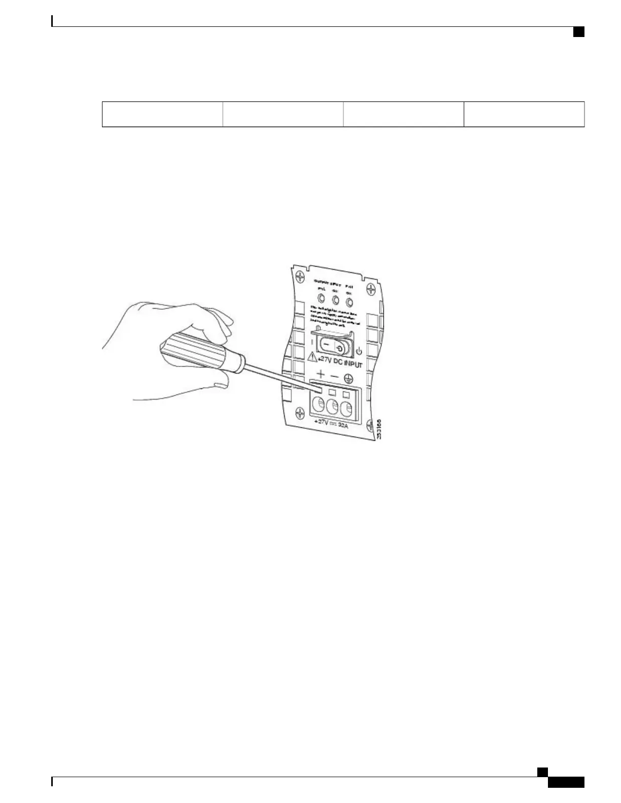
Using a 3.5mm screwdriver, insert the screwdriver at an angle to release the spring while you install the stripped lead
wire as shown in the image.
Figure 108: Inserting a Screwdriver Into the +24 VDC Power Supply Terminal Block
Step 5
Carefully push the screwdriver at an angle forward until you relieve the spring contact.
Step 6
With the screwdriver still inserted, gently push the lead wire (ground lead first) in until the copper wire, as shown in the
image, is no longer visible (see in the following image).
Check that there is no copper portion of the lead wire exposed. You only want the wire insulation visible.Caution
Cisco ASR 1000 Series Router Hardware Installation Guide
267
Cisco ASR 1002 Router Overview and Installation
Connecting Cisco 24 VDC Power Supply

 Loading...


