31-16
Catalyst 2950 and Catalyst 2955 Switch Software Configuration Guide
78-11380-12
Chapter 31 Troubleshooting
Diagnosing Connectivity Problems
To terminate a ping session, enter the escape sequence (Ctrl-^ X by default). You enter the default by
simultaneously pressing and releasing the Ctrl, Shift, and 6 keys, and then pressing the X key.
Using Layer 2 Traceroute
This section describes this information:
• Understanding Layer 2 Traceroute, page 31-16
• Usage Guidelines, page 31-16
• Displaying the Physical Path, page 31-17
Understanding Layer 2 Traceroute
The Layer 2 traceroute feature allows the switch to identify the physical path that a packet takes from a
source device to a destination device. Layer 2 traceroute supports only unicast source and destination
MAC addresses. It determines the path by using the MAC address tables of the switches in the path.
When the switch detects a device in the path that does not support Layer 2 traceroute, the switch
continues to send Layer 2 trace queries and lets them time out.
The switch can only identify the path from the source device to the destination device. It cannot identify
the path that a packet takes from source host to the source device or from the destination device to the
destination host.
Usage Guidelines
These are the Layer 2 traceroute usage guidelines:
• Cisco Discovery Protocol (CDP) must be enabled on all the devices in the network. For Layer 2
traceroute to functional properly, do not disable CDP. If any devices in the physical path are
transparent to CDP, the switch cannot identify the path through these devices.
Note For more information about enabling CDP, see Chapter 23, “Configuring CDP.”
• A switch is reachable from another switch when you can test connectivity by using the ping
privileged EXEC command. All switches in the physical path must be reachable from each other.
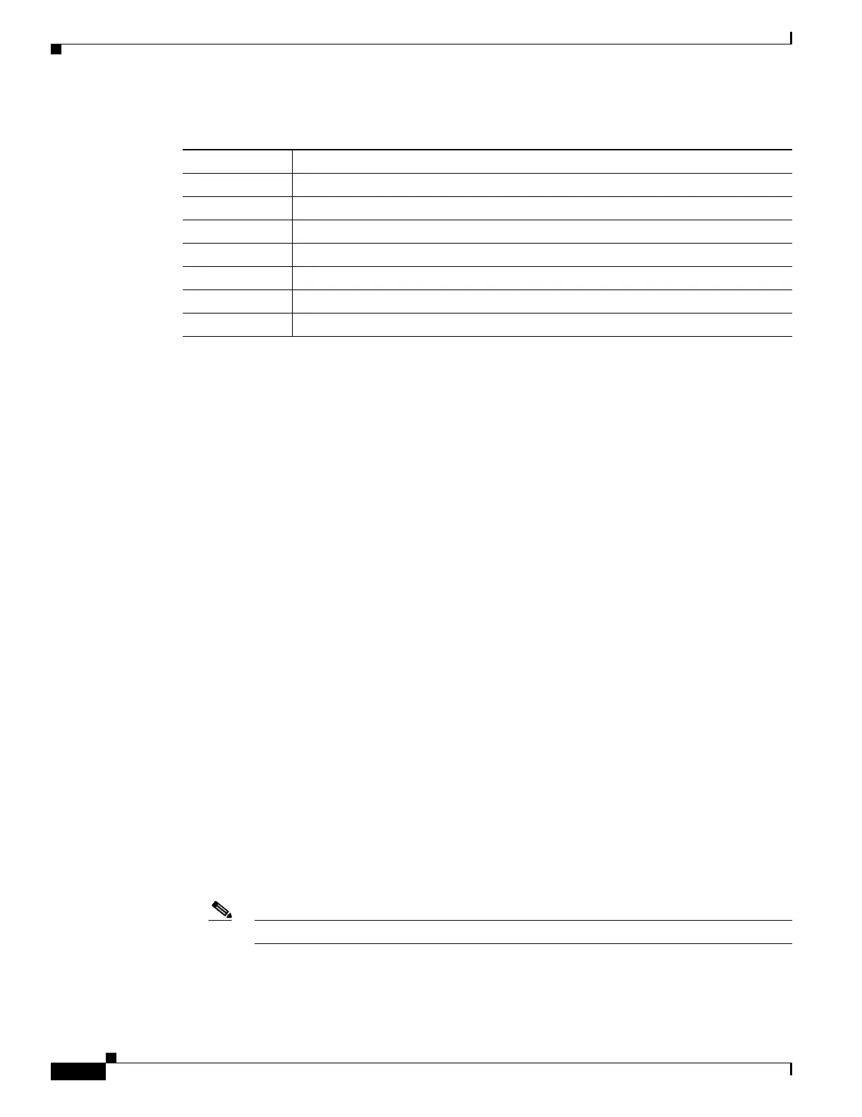
Table 31-1 Ping Output Display Characters
Character Description
! Each exclamation point means receipt of a reply.
. Each period means the network server timed out while waiting for a reply.
U A destination unreachable error PDU was received.
C A congestion experienced packet was received.
I User interrupted test.
? Unknown packet type.
& Packet lifetime exceeded.