4-14
Catalyst 2950 and Catalyst 2955 Switch Software Configuration Guide
78-11380-12
Chapter 4 Assigning the Switch IP Address and Default Gateway
Modifying the Startup Configuration
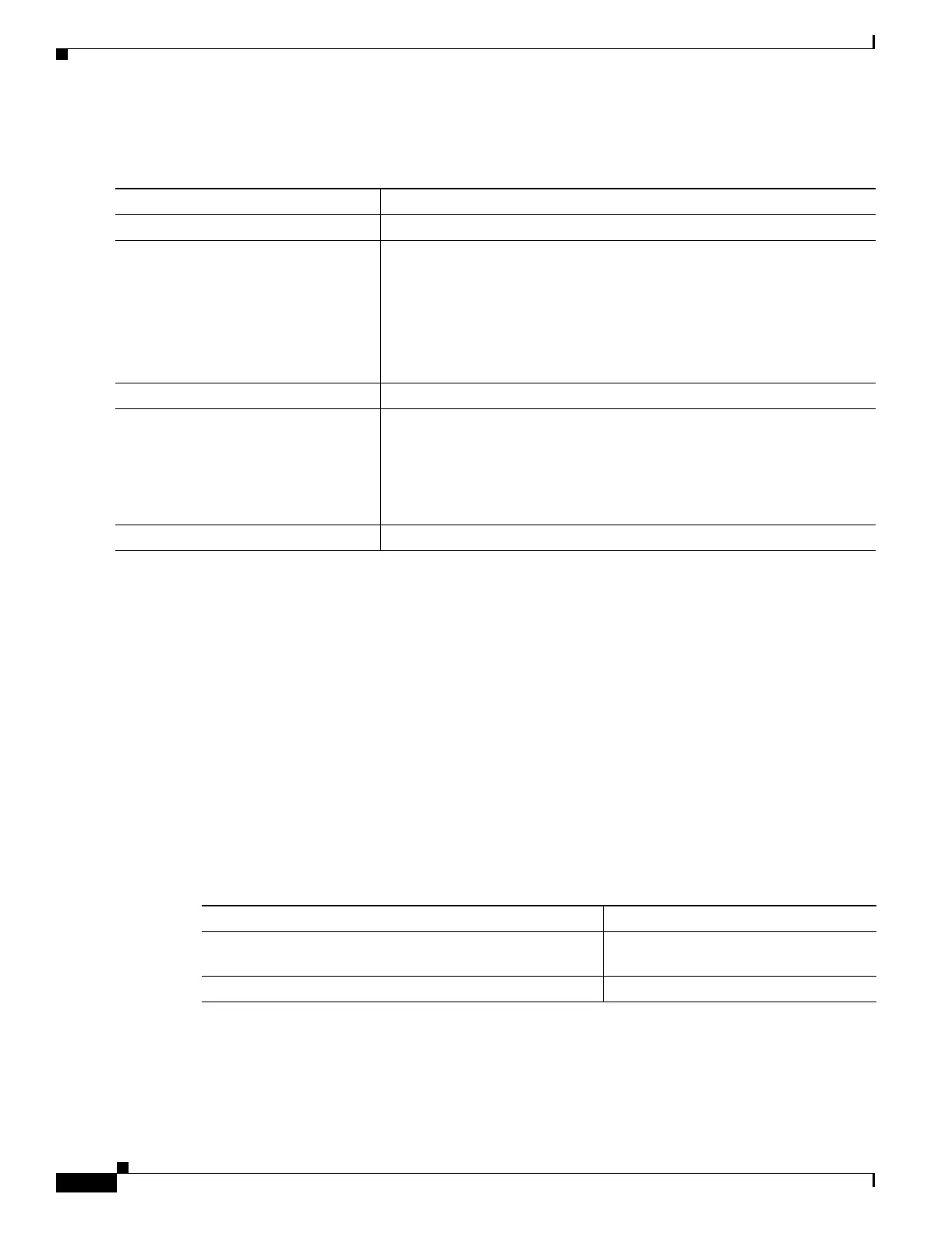
Beginning in privileged EXEC mode, follow these steps to configure the switch to boot a specific image
during the next boot cycle:
To return to the default setting, use the no boot system global configuration command.
Controlling Environment Variables
You enter the boot loader mode only through a switch console connection configured for 9600 bps.
Unplug the switch power cord, and press the switch Mode button while reconnecting the power cord.
Release the Mode button a second or two after the LED above port 1X turns off. Then the boot loader
switch: prompt appears.
The switch boot loader software provides support for nonvolatile environment variables, which can be
used to control how the boot loader, or any other software running on the system, behaves. Boot loader
environment variables are similar to environment variables that can be set on UNIX or DOS systems.
Environment variables that have values are stored in the flash file system in various files as shown in
Table 4-4.
Each line in these files contains an environment variable name and an equal sign followed by the value
of the variable. A variable has no value if it is not listed in this file; it has a value if it is listed in the file
even if the value is a null string. A variable that is set to a null string (for example, “ ”) is a variable with
a value. Many environment variables are predefined and have default values.
Command Purpose
Step 1
configure terminal Enter global configuration mode.
Step 2
boot system filesystem:/file-url Configure the switch to boot a specific image in flash memory during the
next boot cycle.
• For filesystem:, use flash: for the system board flash device.
• For file-url, specify the path (directory) and the name of the bootable
image.
Filenames and directory names are case sensitive.
Step 3
end Return to privileged EXEC mode.
Step 4
show boot Verify your entries.
The boot system global command changes the setting of the BOOT
environment variable.
During the next boot cycle, the switch attempts to automatically boot the
system using information in the BOOT environment variable.
Step 5
copy running-config startup-config (Optional) Save your entries in the configuration file.
Table 4-4 Environment Variables Storage Location
Environment Variable Location (file system:filename)
BAUD, ENABLE_BREAK, CONFIG_BUFSIZE,
CONFIG_FILE, MANUAL_BOOT, PS1
flash:env_vars
BOOT, BOOTHLPR, HELPER, HELPER_CONFIG_FILE flash:system_env_vars