2-21
Catalyst 3750 Switch Hardware Installation Guide
78-15136-03
Chapter 2 Product Overview
Front Panel Description
Stack LED
The stack LED shows the sequence of member switches in a stack. Up to nine
switches can be members of a stack. The first nine port LEDs show the position
of a switch in a stack. Figure 2-11 shows a magnified view of the LEDs on the
first switch, which is member number 8 of the stack. For example, if you press the
Mode button to select the stack member on this switch, the port LED 8 flashes
green because this represents the member number of this switch. The port
LEDs 3 and 4 are solid green, as these represent the member numbers of other
switches in the stack. The other port LEDs are off because there are no more
members in the stack.
When the stack LED is selected, the representative stack LEDs are green when the
StackWise ports (on the switch rear panel) are up, and the representative stack
LEDs are amber when the ports are down:
• SFP port LEDs 1 and 2 on the Catalyst 3750-24TS switch show the status for
StackWise ports 1 and 2, respectively.
• SFP port LEDs 3 and 4 on the Catalyst 3750-48TS switch show the status for
StackWise ports 1 and 2, respectively.
• SFP port LEDs 27 and 28 on the Catalyst 3750G-24TS switch show the status
for StackWise ports 1 and 2, respectively.
• The 10/100/1000 port LEDs 23 and 24 on the Catalyst 3750G-24T switch
show the status for StackWise ports 1 and 2, respectively.
• SFP port LEDs 11 and 12 on the Catalyst 3750G-12S switch show the status
for StackWise ports 1 and 2, respectively.
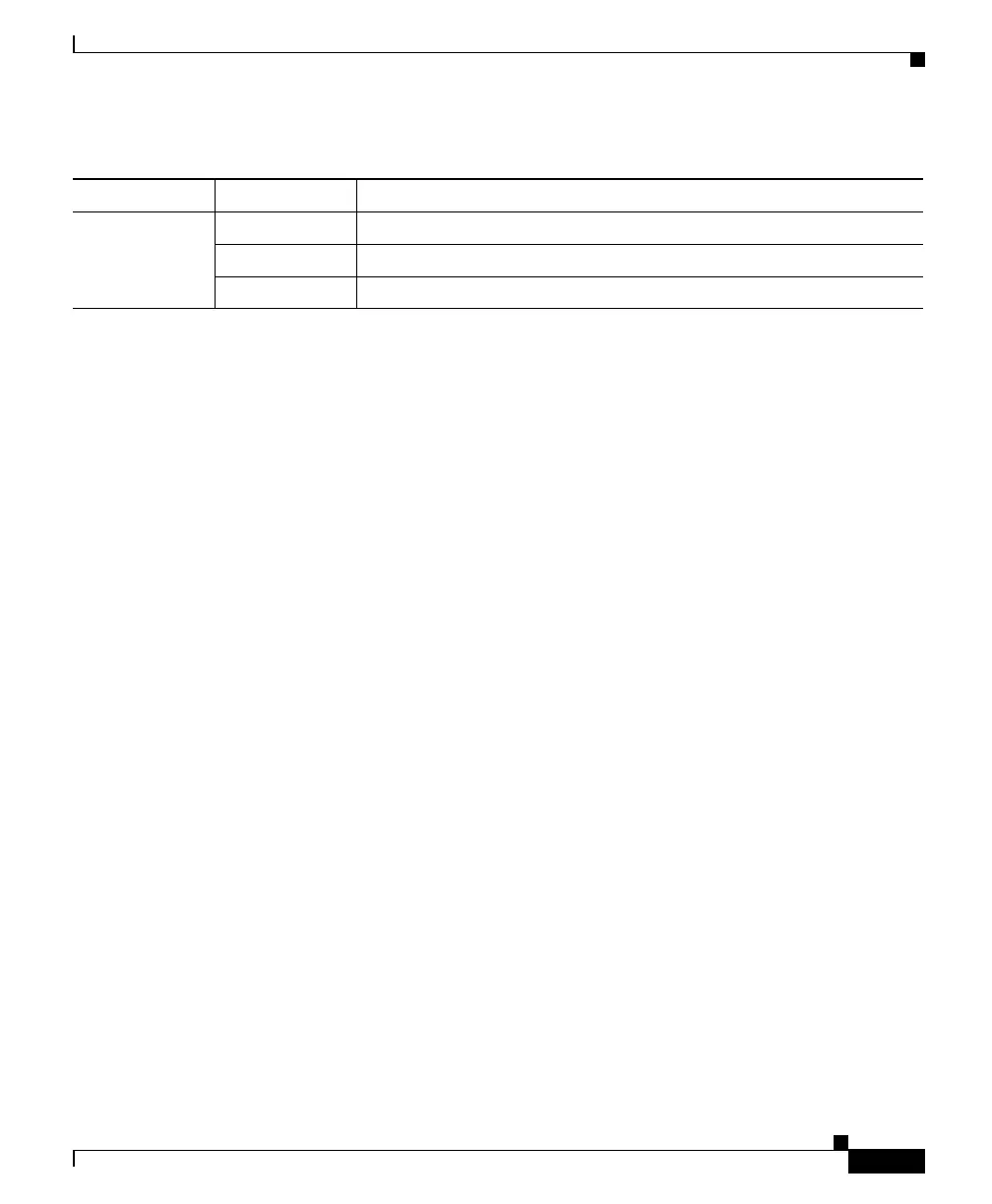
STACK
(stack member)
Off No stack member corresponding to that member number.
Flashing Green Selected switch’s member number.
Green Member number of other stack member switches.
1. The PoE LED is only on the Catalyst 3750-24PS and 3750-48PS switches.
Table 2-6 Meaning of LED Colors in Different Modes on the Switch (continued)
Port Mode Port LED Color Meaning

 Loading...


