Form No. 56043161 - Clean Track
®
L24 - 23
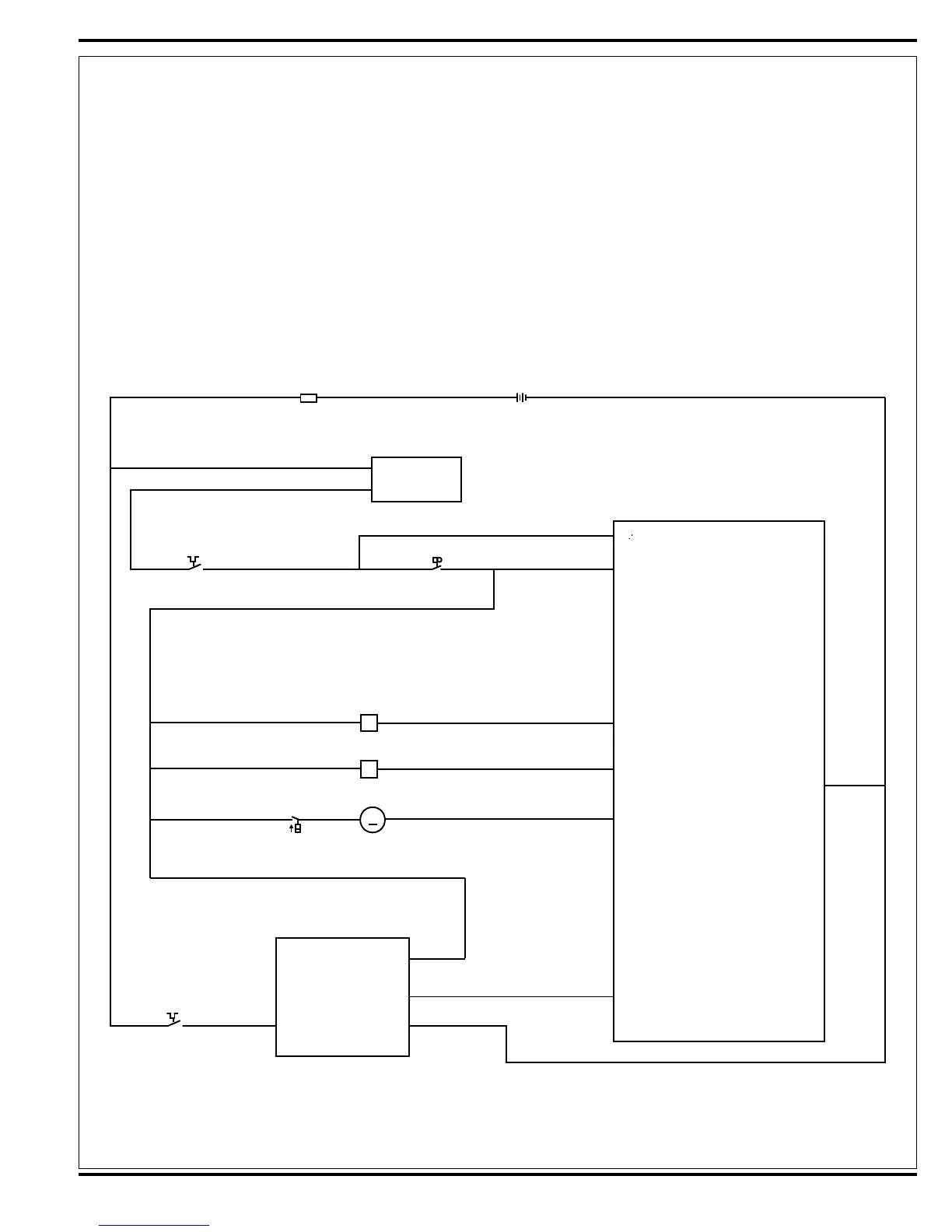
- (Negative) circuit input starts with:
• Battery negative ground inputs at the A1 Control Board and A2 Speed Control Ground terminals.
• The A1 control board solution button enabled.
• A negative voltage output from the A2 speed controller’s (pin #6) RED/BLK wire to the A1 control board RED/BLK
wire (terminal J1-5). Note that the A2 speed control Brake output (pin #6) occurs whenever the R1 direction throttle
pot is moved off its neutral setting.
A negative voltage output from terminal J1-6 GRN/BLK wire is direct to the M1 Solution Pump turning it on to allow
ow to the L1 and L2 Solenoids. Note that the voltage should be the same when one or two nozzles are actuated. The
voltage is a PWM signal at 10KHz.
BRN
BRN
BRN
BRN
Coil, Solution Solenoid I
Fuse, 150 A
B+
Interlock
Circuit Breaker, 10 A. Switch, SPST Key
Onboard
Battery Charger
A1 Control Board
A2 1228 Speed
Control
Coil, Solution Solenoid II
Solution I
B+ Unswitched
B- Switched
Solution II
J1-2
J2-4
J2-8
RED/GRN
RED
RED
GRN
GRN BRN/WHT
BRN/WHT
CB1
RED BLK
BLK
J1-4YEL/GRN
J1-6GRN/BLK
Solution Pump
Ground
Solution Pump
Note: Switch is Part
of Pump Assembly
M1
L2
S3
S1
F1
BT1
L1
Pin 6 - Brake (-) For./Rev.
RED/BLK
RED
B+ B-
WHT/YEL BLK
J1-8
x
M
Circuit Breaker, 30 A.
CB 2
x
+ -
Pin 5 - KSI
BRN
Figure 5
+
+
 Loading...