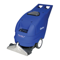
48 - Form No. 56043161 - Clean Track
®
L24
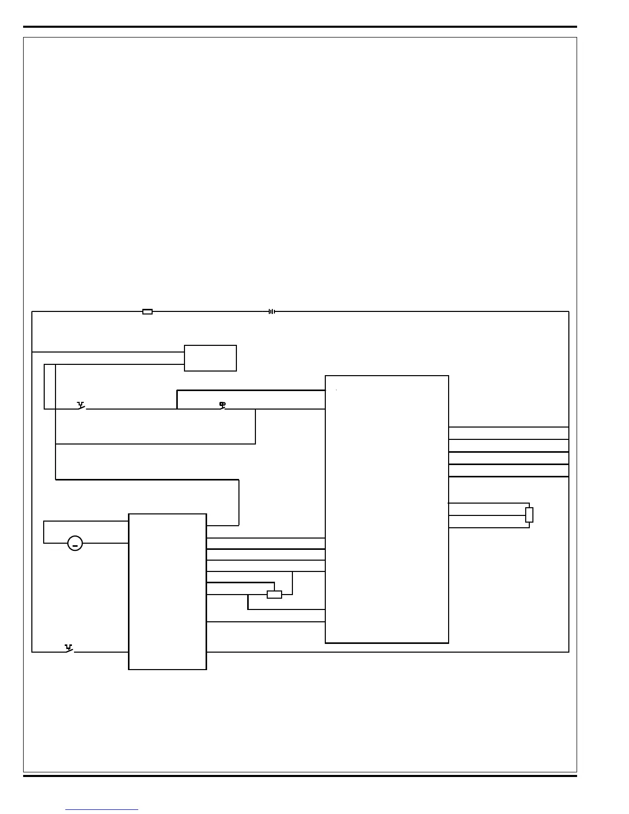
Drive Motor System Function
See Figures 17 and 18. With the Key Switch S1 closed, the BRN wire inputs 24V to the A2 speed controller (pin
5-KSI) to make its internal control circuits operational (powering it up). The CB2 circuit breaker (30-Amp) supplies the
positive load circuit voltage input to the B+ controller terminal (WHT/YEL wire). The black wire from the battery negative
standoff supplies the negative input to the B- controller terminal.
Moving the 5K Ohm R1 pot off its centered balanced neutral setting of approximately 2500 Ohms, activates the
operator input to the speed control. Forward or Reverse movement of the drive paddle rotates the pot shaft, and the
pot’s variable resistance values are changed which generates the internal voltage signals (0-5 Volts) needed for the
controller’s output operation. These control board voltage input signals are what energizes the Forward and Reverse
directional relays, which then select the motor polarity and nal voltage level outputs at the M1 and M2 terminals.
When the operator turns the R2 speed limit Pot from min. to max. (CW) this causes an input resistance relationship
change between the pot high (+) and wiper terminals (high to low Ohms), thus increasing the maximum wheel motor
operating speed range. Turning the knob (CCW) increases the resistance and the motor speed range is reduced.
Electrical Diagram
*For a complete description of all callouts see the Electrical Wiring Diagram/Schematic.
Figure 17
BRN
Fuse, 150 A
B+
Interlock
Circuit Breaker, 10 A. Switch, SPST Key
Onboard
Battery Charger
A1 Control Board
A2 1228 Speed
Control
B+ Unswitched
B- Switched
J2-4
J2-8
RED
RED
GRN
GRN BRN/WHT
BRN/WHT
CB1
RED BLK
BLK
Ground
S1
F1
BT1
Pin 6 - Brake (-)
For./Rev.
ORN/BLU
RED/BLK
RED
B+ B-
WHT/YEL BLK
J1-8
Pin 16 - REV
Reverse
BLU/BLK
J1-9
Pin 13 - Pot Low
Pot Low
WHT
J3-13
Pin 4 - Pot Wiper
BLU
Pin 3 - Pot Hi
Pot Hi
BLK
J3-14
Pin 18 - Spd Limit Pot
SLP Output
BRN
J3-12
J2-5
Pin 9 - Status
Status
J1-7
x
BLK
Ground
J2-6
BLK
Ground
J2-7
BLK
Ground
J3-11
BLK
Ground
J3-2
PINK
Driver Pot High
J3-10
BRN
Driver Pot Input
J3-6
GRA
Driver Pit Low
J3-4
Circuit Breaker, 30 A.
CB 2
x
+ -
Pin 5 - KSI
BRN
BRN/BLK
YEL/RED
+-
M8
M
Motor, Wheel Drive
M1
M2
3 1
2
R1 Pot. 5K Ohm
Throttle
3
1
2
R2 100K Ohm
Speed LImit Pot
+
+
 Loading...