Form No. 56043161 - Clean Track
®
L24 - 47
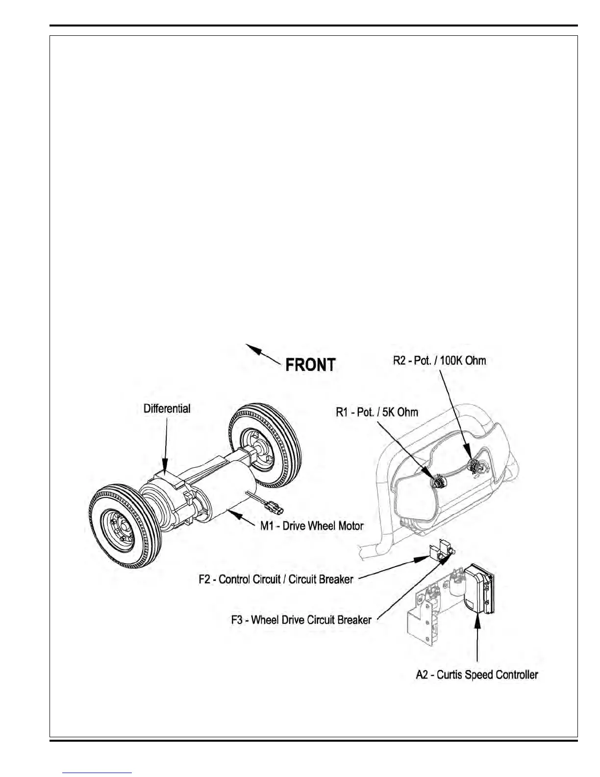
Figure 16
Wheel Drive System
General Functional Overview
See Figures 16 and 17. A 300-watt (.4 HP) permanent magnet (24V) motor transaxle (M8) is used for the wheel drive
on all machines. A Curtis PMC solid-state speed controller (A2) regulates the variable speed and Forward/Reverse
wheel drive motor functions. Location of the controller is in the rear handle housing electrical compartment (accessible
by removing the four screws securing the rear electrical panel). The potentiometer R1 mounted inside the drive paddle
inputs to the A2 controller the machine operator’s throttle (variable speed) and direction demands. A second pot R2
(knob adjusted) is located on the outside of the paddle cover and controls the machine’s maximum transport and scrub
speeds.
 Loading...